CobraNet network design
With millions of Ethernet nodes worldwide, digital audio networks are becoming a common feature of today’s A/V installations. Although the design process is changing within the A/V world, there is still a lot to learn to keep up with the fast growing IT industry.
Being one of the first manufacturers to make use of CobraNet by integrating it into its Audia Digital Audio Platform, Biamp Systems has pioneered the use of digital audio networks for high profile installations. It is our hope to be able to share with you some of the valuable information we learned over the last few years.
In this article, we will answer typical questions and summarize basic CobraNet theory. We will also address the basic knowledge required to design, setup and troubleshoot CobraNet networks with Biamp products.
CobraNet network basics
Definitions
- Ethernet
- Network standard of communication for Local Area Networks (LAN). There are several types of Ethernet for both speed (10Mbps, 100Mps, 1Gbps) or physical medium (Twisted pair, Fiber, Coaxial).
- CobraNet network
- CobraNet is a combination of hardware, software and protocol which distributes many channels of digital audio over fast Ethernet. CobraNet uses standard Ethernet packets and network infrastructure.
- CobraNet interface
- All Biamp products carry the CM1 CobraNet interface, a module allowing buffering of audio into Ethernet packets (CobraNet output) and vice versa, Ethernet packets to digital audio signals (CobraNet input).
- Bundle
- Refers to the basic CobraNet audio transmission unit. A bundle typically carries 8 audio channels. The AudiaFlex DSP platform supports flexible bundles ranging from 1 to 8 channels.
- Unicast bundle
- Supports a one to one (1 source and 1 destination) routing of audio on the network. Unicast bundle numbers range from 256 to 61439.
- Multicast bundle
- Supports a one-to-many (1 source but multiple destinations) routing of audio to the network. Multicast addressing consumes network bandwidth and usage. It is recommended that you do not have more than 4 multicast bundles on a switched network. Multicast bundle numbers range from 1 to 255.
- Network latencies
- Three deterministic network latencies, resulting from the buffering of Audio into Ethernet packets, are available for setup on a CobraNet network: 5-1/3, 2-2/3 and 1-1/3 ms.
- Auto-negotiation
- Process during which one device tells another device if it is capable of Full/Half duplex and determines connection rate (10/100/1Gbps). CobraNet interfaces and many network devices undergo this process.
- CobraNet conductor
- The interface supplying the master clock. There is only one conductor per network, the conductor is the device which has the highest conductor priority. Multiple devices may share conductor priority level (a value defined between 1 and 255) but only one device will elected as the conductor. In situations where a network has been oversaturated with CobraNet data it is possible for multiple Conductor instances to appear, causing jitter, crackle, and noise issues. Conductors can be identified in CobraNet Discovery "Disco" software and in Wireshark using the display filter "eth.dst == 01:60:2b:ff:ff:00".
CobraNet in numbers
CobraNet interface channel count:
32x32 I/O channels are available at 5-1/3ms and 2-2/3ms latency.
A total of 32 channels (e.g.32x0, 16x16, 24x8...) are available at 1-1/3ms latency when using fixed 8-channel bundles.
CobraNet network channel count:
64x64 channels (for total of 128 channels) over a single 100Mbit link.
Greater channel capacities are possible over a Gigabit link.
Cable run distance limitations: 100m for CAT5/6 or 2km for multimode fiber
Sample rate: 48kHz
Resolution: 20 bits
Conductor priority: Biamp Audia = 48; Biamp Tesira = 245; Biamp EXPI, EXPO, Vocia = 32
Latency: Audia and Tesira CobraNet latency is user defined, fixed at 1.33ms, 2.66ms, or 5.33ms. Vocia is always 5.33ms.
CobraNet software tools (non-Biamp)
CobraNet Discovery Utility ("Disco"): A monitoring and maintenance tool to discover CobraNet interfaces on a network, upgrade their firmware or simply monitor activity. It is certainly a useful tool during any network troubleshooting exercise.
CobraCAD: This software application allows one to simulate a CobraNet Network and verify CobraNet compliance of a network design.
Both software applications are available for free download on the Cirrus logic website.
Network design guidelines
System design guidelines
When designing CobraNet networks, remember the following simple requirements:
Provide a dedicated switched network infrastructure for CobraNet. It will prevent possible network dropouts or failure triggered by other Ethernet data. The network must be operating, at a minimum, over industry standard Fast Ethernet (100BaseTX/FX).
Use quality switches only (from proven manufacturers). Hub based repeater networks limit performance and the minimal cost difference between a switch and a hub does not justify using hubs anymore.
Installation guidelines
CAT5/6 cable plant
- Cable runs should not exceed the 100m distance limitation.
- Follow recommended industry practice and wiring standards already established by IT industry.
Fiber optics
When using Simple Media Converters (SMC) as a fiber optic to CAT5/6 interface, remember that auto-negotiation with other network devices will not automatically take place over fiber and needs to be manually configured for full duplex communication.
Network performance
Poor quality of the cable plant, EMI and RFI susceptibility, and pull force or bend radius are all factors that could degrade network performances. Pay attention to these factors to improve the quality of your CobraNet network and prevent data packet loss.
Device to device connections
Audia family CobraNet ports do not support auto-MDIX. If two Audia family CobraNet endpoints (AudiaFlex, EXPI, EXPO, etc.) are connected directly to one another it requires the use of a crossover Cat-5 cable. If a switch is placed between the devices straight-through Cat-5 cables should be used.
Tesira SCM-1 cards do support Auto-MDIX and can be connected directly to an Audia device CobraNet port with a straight-through cable. The Tesira port will auto-detect the need to cross-over and do so.
CobraNet in Audia software
Basic block 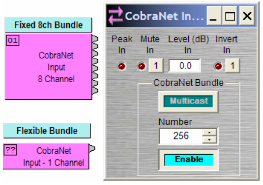

Besides gain, mute, and phase settings, the dialog box of a typical CobraNet I/O includes bundle type (Unicast/Multicast), bundle number and an enable toggle button. Latency setting needs to be configured for the system in the Equipment Table. (The default latency can be set in Tools > Options > Compile).
EXPI / EXPO
If connecting EXPI/EXPO units to an AudiaFlex frame, remember to manually specify the latency settings and bundle number with the scroll wheel on the front panel of each EXPI/EXPO unit. Remember to double check the bundle assignment.
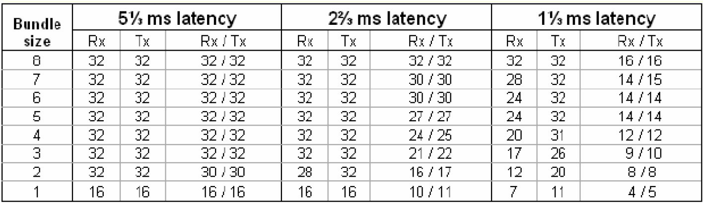
Flexible bundles and network latency
Although flexible bundles allows the reduction of the size of a typical CobraNet bundle (8 channels), there are also limitations.
The following table (also available in the System Network Consideration of the Help file) summarizes limitations of the CobraNet interface and their corresponding network latencies when using flexible bundles. Note for example that the interface will only be able to send and receive 16 x 1 channel bundles as a maximum.
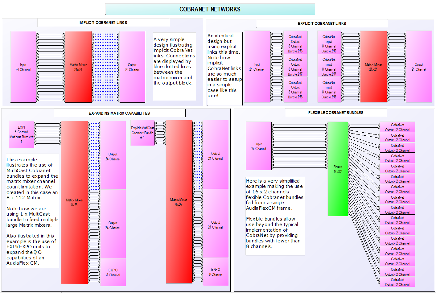
Implicit vs explicit CobraNet bundles
Two types of CobraNet bundles may be used by the DSP platform:
- Explicit links: CobraNet bundles manually set by the designer when using the CobraNet input/output block.
- Implicit links: CobraNet bundles automatically configured by the compiler during compilation. They typically appear as a blue dotted line on your design and do not require any bundle assignment. Implicit CobraNet links use unicast private bundles that are not accessible to users or any CobraNet enabled product. They are a key advantage of the AudiaFlex platform; allowing one-page, multi-unit system design without the hassle of setting up manual links.
Compiling process and CobraNet information
Once compilation is successful, useful information becomes available to the designer.
- Implicit CobraNet links are displayed in the configuration design file with a blue dotted line.
- Latency settings are shown in Tools > Layout Compile Results... or immediately after compiling the system. It's good practice to confirm that you have the expected settings. Latency settings are changed in the Equipment Table.
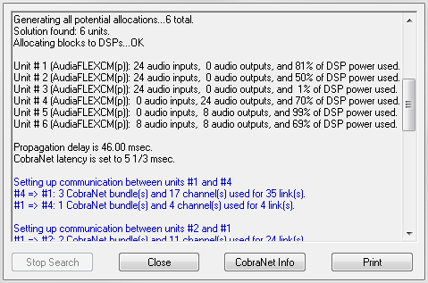
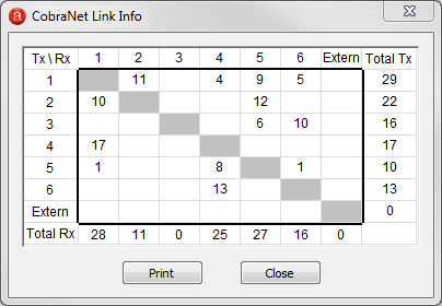
- The CobraNet Link info (Tools > Options > Compile > “Display CobraNet Info”) of the Layout Compile Results indicates the total number of transmitted (TX) and received (RX) channels on a per unit basis. This allows one to quickly evaluate the resources and limitations of the current CobraNet configuration.
Advanced CobraNet network design
Managed switches
Basic network switches suffer from a number of issues:
- Single point of failure, e.g. if one link becomes faulty, the network may be partitioned
- No management solution available for network flooding
- Bandwidth choke points when excessive data traffic is forced down a single link
To combat these issues, the following tools have been implemented in managed switches:
- Spanning Tree Protocol (STP) maintains the active links of the network as a tree while allowing physical loops for redundancy. If available, enable STP to prevent loops from occurring on the network and allow the STP algorithm to figure out a new route in case of link failure.
- Virtual LAN (VLAN) are logically independent networks that allow the designer to segment a network without physically re-arranging it. They may be used with CobraNet networks to allocate dedicated bandwidth requirements on a shared network. Setting up a VLAN requires advance networking skills that a designer will need to learn prior installation.
- Trunking (also called link aggregation) allows two or more parallel links between switches to behave as a single link. The most typical application is to increase bandwidth performance.
Redundant networks
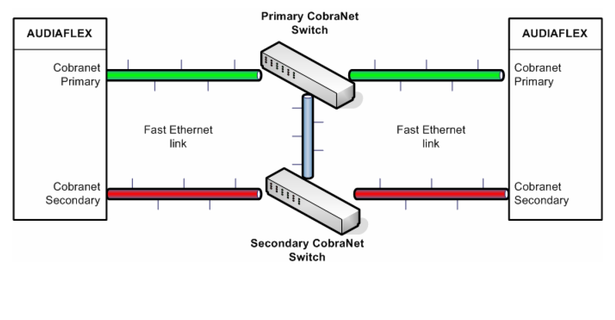
Network redundancy is nothing out of the ordinary for the IT industry. It has already been addressed with the introduction of proven network topologies, monitoring tools or built-in features for switches (as listed above). CobraNet interfaces on AudiaFlex products also include a redundant (secondary) network link to allow automatic switch over in case of a link failure.
The following block diagram illustrates the typical CobraNet network for redundant systems. (Note that redundant links have dedicated switches and Spanning Tree Protocol is required to enable the link between switches to work properly.)
Troubleshooting CobraNet networks
The following section highlights basic network troubleshooting techniques for typical CobraNet network failures:
- Check integrity of the link by looking at the CM1 LEDS (located on the RJ45 connectors). There are multiple versions of CobraNet cards which have been produced over the years and LED indicator functionality has varied. Look for a label printed on the device to show expected activity for the LEDs.
- Simple troubleshooting tools such as a network cable tester or software network analyzers may be a good start to probe your network and determine what may be causing problems such as network drop outs or faulty CobraNet links.
- If using managed switches, check the configuration of each switch to ensure all ports are configured for auto-negotiation.
- If audio sounds distorted at all levels, your network may be experiencing network dropouts resulting from exceeding bandwidth of a link or faulty cable plant. Use CobraNet Disco to determine if the CobraNet interfaces are displaying errors.
- In situations where a network has been oversaturated with CobraNet data it is possible for multiple conductor instances to appear, causing jitter, crackle, and noise issues.
- If the CobraNet link is active, but no audio is passing through, make sure the bundle assignment is correct.
- Finally, if none of the above recommendations fixes the issue, contact the technical support group for suggestions on how to troubleshoot the system.
Understanding CobraNet Disco error codes
Ensure you are using CobraNet Disco 4.0 or later to connect to the CobraNet network.
Note the errorCode shown for the device of concern, all devices will display the last errorCode they experienced whether it is an active error or not. Active errors can be seen because their errorCount value will be greater than 0. It will typically be incrementing higher as time passes and more errors are logged.
Refer to the CobraNet Programmer's Reference Manual for error codes. See Section 9.3 for Error Code Listings.
You can convert the error code hex values to decimal values using an online converter such as http://www.binaryhexconverter.com/hex-to-decimal-converter
CM-1 (Biamp Audia Flex CM and Tesira SCM-1 use the CM-1 chipset)
1. Read Hexadecimal error code 0x220002 in Disco
2. Convert the FIRST two digits of the Hexadecimal value 0x220002 to decimal notation; 22 => 34
3. Look up byte code 34 in Programmer's Reference Manual and see that 34 = Beat Flooded
CM-2 (Biamp EXPI, EXPO, EXPI-O, and Vocia hardware use the CM-2 chipset)
1. Read Hexadecimal error code 0x1022 in Disco
2. Convert the LAST two digits of the Hexadecimal value 0x1022 to decimal notation; 22 => 34
3. Look up byte code 34 in Programmer's Reference Manual and see that 34 = Beat Flooded
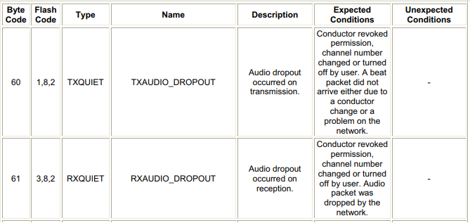
Refer to the Expected Conditions and Unexpected Conditions columns for assistance in interpreting the error.

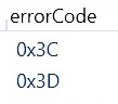
A common error seen is audio dropout on transmit (0x3C => 60) or receive (0x3D => 61). This indicates network problems affecting CobraNet traffic. This may be due to network diameter or other issues related to latency.
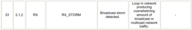
Error 0x21 indicates a broadcast storm was detected and must be rectified.
Error:1002 CM1 WDOG
This is the most common error seen on the front panel of an EXPI or EXPO on a CobraNet system. It means that the host processor has seen the CM-1 module crash.
Most likely this error is caused by a network that has been flooded with an excess of broadcast traffic which has crashed the device. This is also referred to as a "broadcast storm". A broadcast storm can be caused by a hard-wired loop inadvertently created somewhere in the network.
- If you disconnect the unit from the CobraNet network, reboot it, and the error persists (while disconnected from the network), then you have a hardware failure.
- If you disconnect the unit from the CobraNet network, reboot it, and the error is gone, but then reappears when re-connected to the CobraNet network you are suffering from the broadcast storm scenario.
In the event you have a broadcast storm and it is the result of too much network traffic, you will need to analyze the network traffic and potentially segregate the traffic to reduce it to allowable levels.
One channel of CobraNet data uses approximately 1.5625Mbps for 20-bit 48kHz audio.
32 channels x 1.5625Mbps = 50Mbps
32+32 channels x 1.5625Mbps = 100Mbps
Because switches are full-duplex devices, up to 64 channels of 48KHz, 20-bit audio can be sent over a single 100Mbit link in each direction. This means 128 audio channels over a single CAT5 cable.
Additional troubleshooting for CobraNet can be found at Cirrus Logic's Troubleshooting page.
http://www.cobranet.info/support/installation/troubleshooting#loop_network
http://www.cobranet.info/support/design/switched_networks#spanningTree
DAP file sample
To better illustrate concepts presented in this article, we've created an example .dap file that includes:
- Using Multicast and Unicast CobraNet bundles
- Using flexible bundles to maximize your design
- A clever combination of multicast bundles and matrix mixers to create large matrices
- Implicit vs explicit CobraNet bundles
- Improving network latency within a design by fixing unit assignment
- Using EXPI/EXPO to expand the I/O capabilities of an AudiaFlex
A screenshot of the example file is shown below: