Wiring switches to the Logic Box and Voltage Control Box
Wiring a generic switch
Wiring generic, off-the-shelf switches to either the Logic Box or the Voltage Control Box (logic pins only) is very straightforward. Each switch should be wired between the ground terminal and the proper logic pin as indicated in the picture below. Switches and buttons are always wired to logic inputs, starting with logic input 1 and progressing to the right. Any ground terminal can be used for the ground connection.

Wiring an RP-S4
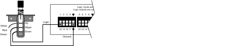
The Biamp RP-S4 is a wall plate with four double-pole/double-throw (DPDT) switches. These switches are prewired from the factory with the poles tied together so it works as a single-pole/double-throw (SPDT). Each switch has three wires: white, red and green. The red wire is common while white and green are the contact wires. When the switch is pressed, a short will be present between the red and green wires. Releasing the switch will break that connection and short the red and white wires. For most applications, only the red and green wires need to be connected to the ground terminal and the logic input terminal of the Logic Box or Voltage Control Box respectively as shown below.
Further reading
Once the device is physically connected to the Logic Box, you'll need to program it. See Logic Box Programming for more information.
Wiring LED's and relays to the Logic Box and Voltage Control Box