AudiaFUSION software configuration
The Audia software provides the interface for configuring and programming AudiaFUSION. A single software block has been added to the software for AudiaFUSION, but as we’ll see below, it comes in several flavors.
Initialization Properties dialog
The Fusion block can be accessed from the I/O menu in the Device Toolbar just like any other input or output block. Dropping a Fusion block into a configuration file will open its Initialization Properties dialog, where the block’s attributes can be defined.
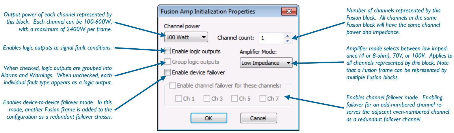
Logic outputs
Depending on how a Fusion block is initialized, its appearance can vary greatly. Firstly, each Fusion block displays its channel count, output power level, and impedance (LZ-Low Impedance, CV-Constant Voltage). Note that all channels represented by a single Fusion block will have the same output power and impedance.
Next, you’ll notice that the three example blocks below have different logic outputs, which is a result of different logic initialization settings. The left example block does not have logic outputs enabled, which is the default state. The middle example block has logic outputs enabled and grouped, which results in a single Alarm and Warning logic output per channel. The right example block has logic outputs enabled and ungrouped, which gives each fault type its own logic output per channel. See the table below for a detailed description of each logic output.
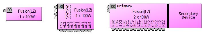
Failover
Selecting channel or device failover in the Initialization Properties will also change the appearance of the Fusion block. When no failover is enabled, the Fusion block will look like the top example block.
Fusion blocks with channel failover enabled have primary (P) and secondary (S) inputs, and the secondary inputs are grayed out. The secondary inputs are a reminder that the second channel of the pair is being reserved for failover, and audio will be automatically routed to the second channel when an alarm is raised.
Fusion blocks with device failover enabled have another entire block attached to them with no inputs or outputs, labeled “Secondary Device.” This secondary device is a reminder that there is another identical Fusion frame that is being reserved for failover, and audio will be automatically routed to the second device when an alarm is raised.
After a failover has occurred and the problem which triggered the failover has been fixed, Fusion will not automatically switch operation back to the primary channel or device. Instead, the device(s) must be power cycled so that it can re-check the primary channel/device for failover conditions.
Control dialog
After inserting the Fusion block into your configuration, double-click on it to open its Control Dialog window:
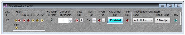
- Device IO
- Similar to other input and output blocks in Audia, the Device IO column correlates the Fusion software block to the physical amplifier channel. This is useful in determining amplifier channels when a single Fusion device is broken up into multiple software blocks.
- Pri/Sec
- The Primary/Secondary indicator only appears in Fusion blocks which have failover enabled, and it indicates which channel or device is currently being used.
- Faults
- This section indicates any active warning or fault conditions. Yellow indicators show warnings, and red indicators show alarms. See the table below for fault definitions. Additionally, a test button is available for each channel which can be used to simulate an alarm and trigger a failover.
- Clip Limiter
- This button engages a limiter to prevent amplifier clipping. The threshold of the limiter is set such that any signal peaks which would have clipped the amplifier are attenuated.
- HS Temp % Max
- This field indicates the heat sink temperature in terms of a percentage of its maximum allowed temperature. A heat sink warning will occur if this percentage exceeds 92%, at which point audio will automatically be attenuated by 3dB. If this percentage reaches 100%, then an alarm will be triggered, audio will be stopped altogether, and a failover will occur (if enabled). Heat sink alarms and warnings are cleared when the heat sink temperature drops below 84%.
- Clip Count Threshold
- This setting determines how much clipping needs to occur before the Excessive Clipping (EC) warning is triggered. In order to trigger the warning, the number of consecutive 100 ms segments of audio which contain clipped audio samples needs to exceed this threshold.
- Gain Out
- A digital level control which applies gain to the audio signal before it is amplified. See the discussion on Output Gain below.
- Impedance Parameters
- This section deals with Fusion’s impedance monitoring features, which are discussed in more detail in the Audia Fusion Impedance monitoring article. The Control Dialog window allows you to see if impedance monitoring is active (IMA), and how many bands are being monitored.
| Label | Warning | Alarm | Description |
| FSR | yes | Fan Stuck Rotor—indicates a malfunction with an internal fan. | |
| HS | yes | yes | Heat Sink—warning indicates heat sink is at 92% of its cooling capacity. If heating continues to 100%, HS Warning turns intoan HS Alarm, and audio is stopped. Heat sink temperature must drop to 84% before either warning or alarm is cleared. |
| SC | yes | Short Circuit—indicates that the effective impedance is less than 1 ohm, or that current has exceeded the maximum threshold. | |
| CF | yes | Channel Failure—indicates unspecified hardware failure of an AM-600 amplifier module. | |
| EC | yes | Excessive Clipping—indicates that amplifier output clipping has occurred in excess of the Clip Count Threshold parameter. | |
| LZ | yes | Low Impedance—indicates that the impedance monitoring circuit has detected an impedance that has dropped below the user-specified tolerance range. | |
| HZ | yes | High Impedance—indicates that the impedance monitoring circuit has detected an impedance that has risen above the user-specified tolerance range. | |
| AL | yes | Alarm—only available when using grouped logic outputs. This output is a logical OR of the HS, SC, and CF outputs. | |
| WN | yes | Warning—only available when using grouped logic outputs. This output is a logical OR of the HS, EC, LZ, and HZ outputs. | |
| PDG | Primary Device Good—only available when using device failover mode. Indicates that the primary device is running without warnings or faults. | ||
| SDG | Secondary Device Good—only available when using device failover mode. Indicates that the secondary device is running without warnings or faults. |
Output gain
In an Audia system, clipping occurs at +24dBu, and subsequently AudiaFUSION has been designed to deliver maximum rated output power when it is being fed with a +24dBu signal. However, in practice, most Audia systems with proper gain structure have audio levels which normally hover around 0 dBu. In the world of amplifiers, having 24 dB of headroom means a lot of wasted power.
So, we’ve added a digital gain (labeled Gain Out) to the Fusion output block to help you use more of the amplifier’s output power. Keep in mind that this is digital gain, the same as if you added a level control block right before the Fusion block. The Gain Out setting has a range of 0-24dBu, and by default it is set to 12. This is important to be aware of, because setting this value to 12 effectively lowers the clipping point of the system to +12dBu. Similarly, if the Gain Out was set to its maximum value of 24, then the clipping point of the system would be lowered to 0 dBu.