Automixer basics
This article describes functions and common usage techniques for the Automixer control block for Audia and Nexia products.
For more information about automixers on the Tesira platform, please check out Gain Sharing vs. Gating Automixers.
Automixer benefits
Automatic mixers (Automixers) have the following three benefits: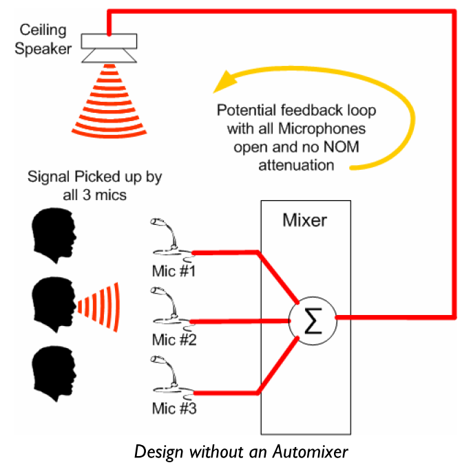
- Improved Signal to Noise Ratio (SNR) by limiting the Number of Open Microphones (NOM)
- Improved gain before feedback by providing gain attenuation with respect to the NOM (i.e. NOM attenuation)
- Reduced microphone comb filtering by limiting voice pickup to a single microphone
Typically Automixers should only be used for installations with multiple microphones.
Let's look at some potential issues with a system without an Automixer:
- Poor SNR with all microphones picking up ambient noise.
- Poor gain before feedback with multiple potential feedback loops.
- The voice signal is picked up by multiple microphones and suffers from multi-path interference, also called comb-filtering.
The Automixer is designed to combat these common issues. In a system with an Automixer, you can realize these benefits: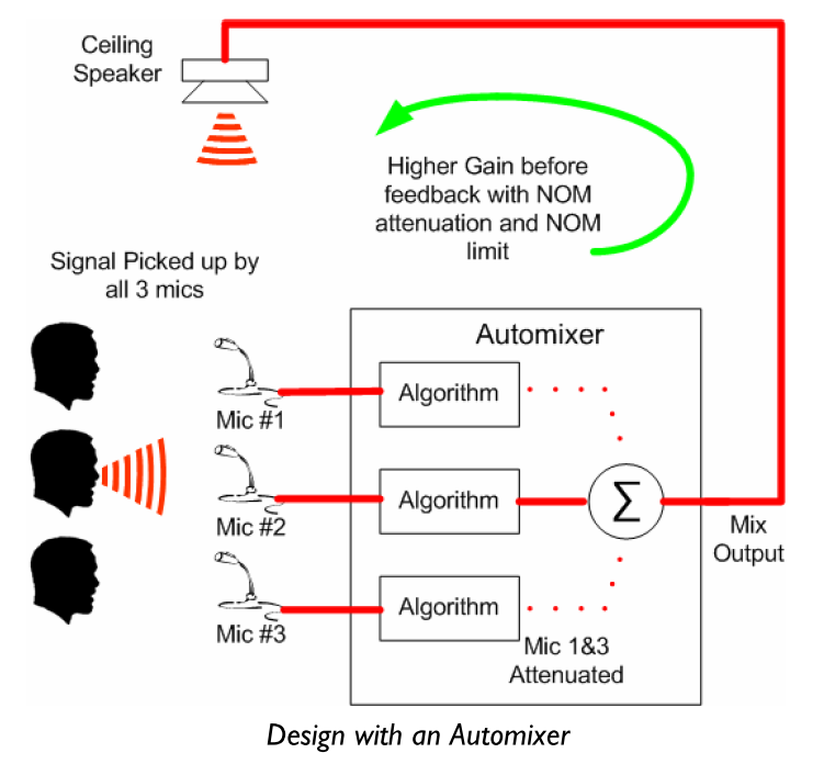
- Optimized SNR by attenuating unused microphones (dotted lines), hence lowering noise pickup.
- Optimized Gain before feedback with the introduction of NOM (number of open mics) attenuation.
- Reduced comb-filtering with single microphone pick up.
Automixer block diagram

- First, the microphone input signal is split into a side chain filter for RMS detection and Threshold comparison.
- The RMS level of the signal is sent to a Threshold Calculator which computes the current threshold for all channels. The new threshold value is then updated back to the Side Chain detector for each channel of the Automixer. In other words, the exact same threshold is applied to input channels of all microphones.
- Using the updated threshold, the Side Chain controls the VCA by deciding the Microphone’s state.
- If the RMS level is above threshold, the Mic state is ‘Open’ i.e. the VCA applies no attenuation to the signal.
- If the RMS level is below threshold, the Mic state is ‘Attenuated’ i.e. the VCA applies an ‘Off Attenuation’ to the signal.
- Note: Biamp’s Automixer algorithm attenuates the signal using a ramped VCA. The resulting behavior is a smooth transition from one state to the other.
- The Microphone’s state (Open/Attenuated) may also drive a corresponding logic output. (Ch1 starting from the left side)
- The threshold decision in Side Chain sends the Microphone state to a NOM Calculator, which simply computes a global NOM count for the entire Automixer. This ‘Current NOM’ is then used to calculate the NOM Attenuation.
- Finally, all channels are mixed to a common Mix bus (labeled “M”) on the output side.
- One to one direct outputs (not mixed with others) are also available at 2 different stages of the audio chain (pre-NOM or post-NOM)
Adaptive Threshold Sensing (ATS)
The Adaptive Threshold Sensing (ATS) method refers to the decision making process of the microphone’s state. The ability to discriminate the ambient noise from the beneficial signal (i.e. voice of speaker) is based on constant scanning of the input channels for the highest RMS level. The algorithm is said to be “adaptive” as it dynamically adjusts its threshold depending on the overall ambient noise floor. This explanation hopefully highlights how much proper gain structure matters to the performance of the algorithm. The usage of levelers is strongly recommended on the input side to provide consistent signal to the Automixer.
NOM Attenuation
A simple statement rules the NOM attenuation process.“Attenuate by 3dB for every doubling of the Number of Open Microphones”
It translates to the following mathematical formula: NOM attenuation = 10log(NOM)
Let’s use a couple of examples to better illustrate the NOM attenuation:
- 1 active microphone means no attenuation: 10log(1) = 0dB
- 2 active microphones translates to doubling the NOM, i.e. 10log(2) = 3dB of attenuation
- 4 active microphones translates to doubling the NOM again, i.e. 10log(4) = 6dB of attenuation
Once the limit of 8 active microphones is reached (9dB Attenuation), the NOM count and attenuation maximum is reached and will not increase further. (Hopefully, the 8 persons trying to talk at once will have figured out the same by then…) If more mics are present the NOM process will always limit the number of open mics to 8.
Mix Minus design using direct outputs
The concept of Mix Minus relates to a common technique for optimizing gain before feedback in voice lift application (microphones locally reinforced).
In a Mix Minus design, microphones are attenuated, or simply not routed, to the ceiling speaker zones nearby.
The simplified diagram shown is an illustration of such system, where Mic #1 is only routed to ceiling speaker Zone #2 and inversely for Mic#2. With this configuration, we increased the direct microphone to speaker distance therefore decreasing the potential for feedback.

An Automixer with enabled direct outputs is a perfect match for creating Mix Minus designs.
Activate it either from the Automixer block’s initialization dialog box or via right click + Edit Block Parameters.
Automixer settings
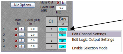
The basic settings of an automixer include a mute and level control for each input, and a mute and level control for the Mix output. The Bus column allows control over whether or not each input is included in the Mix output.
Mic Options
 Mic Options are available from the Automixer dialog box and include settings for:
Designated Mic ON / Last Mic Hold: Use this setting to decide which microphone channel will remain ON when no signal is present at any input. (Default setting is None)
Open Mic Limits: An Open Mic limit may be set by the designer to control the maximum NOM. Warning: Setting this value must be done with care as it might impact on the Automixer’s performance.
Edit Channel Settings
Channel Settings affects individual channel settings, but may be applied to all channels by choosing the "Set All" option. Per channel settings are available to the programmer by right clicking on the Mix bus cross-point.
Within the Channel Settings dialog box, the following options are available:
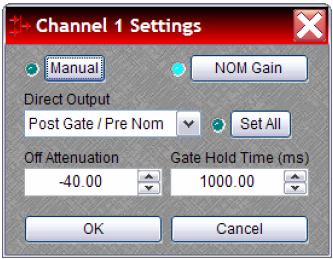
- Manual turns on/off channel gating. When enabled (Blue LED ON), the microphone state for this channel remains ON at all times (i.e. VCA attenuation is turned bypassed) and its level does not contribute to Threshold or NOM attenuation.
- NOM Gain turns on/off channel contribution to NOM (number of open mics) attenuation. When enabled (Blue LED ON), NOM attenuation is applied to this signal. Turning NOM Gain OFF for this channel would not count this microphone channel in the NOM gain attenuation formula (-10log (NOM)) and would turn NOM attenuation OFF.
- Direct Output designates the channel's direct output signal path as:
- Post Gate / Pre NOM: After the VCA but before the NOM attenuation
- Post Gate / Post NOM: After the VCA and after the NOM attenuation
- Off (Direct Outputs must be enabled when placing Auto Mixers from the Object Toolbar for the Post Gate options to be present.)
- Set All causes current Channel Settings to be applied to all channels in the Automixer.
- Off Attenuation determines the amount of attenuation applied when channel is inactive. By default set to -40dB, this setting controls the behavior of the VCA. Unless you are perfectly aware of what you are trying to achieve, we do not recommend changing this value.
- Gate Hold Time determines length of time before channel becomes inactive, once signal is no longer present. By default set to 1000ms, this setting controls the behavior of the VCA. Unless you are perfectly aware of what you are trying to achieve, we do not recommend changing this value.
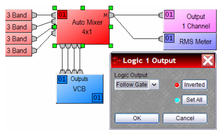
Logic outputs
The logic outputs on an auto mixer provide feedback for when an input channel is gated on or off.
Confidence LED
System designers might want a visual indication of the state of the microphone (Open / Attenuated).
By enabling logic outputs on the Automixer (feature available from the block’s initialization dialog box), logic outputs could, for example, follow the state of the microphone: Open = 1 (high) and Attenuated = 0 (low). Simply connecting the Logic outputs to a VCB / Logic Box driving an LED will provide visual indication on whether the microphone is Open or Attenuated.
Pan-tilt-zoom (PTZ) camera tracking
Integrating camera tracking to your design is only a couple of clicks away with the help of the Automixer’s logic outputs and the command string blocks.
In this example, connecting the logic outputs to the command string block will trigger a command to be sent to a camera or camera controller, so that the camera can pan to the active microphone location. The addition of Logic Delay blocks can improve this functionality and provide smoother behavior, for example, a mic would have to stay active for a set period of time before the camera moves to the set position.
Audia/Nexia systems offer one way of signaling or triggering cameras: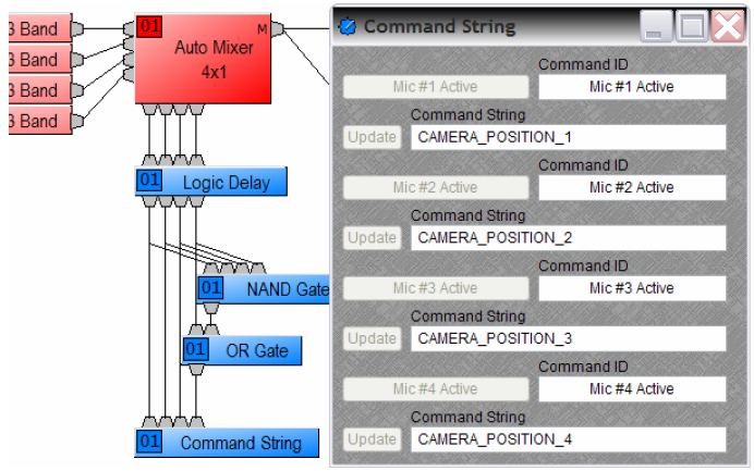
RS-232
- Using the 'Command String' block and the serial port on the processor either directly linked to a camera with a serial port or linked to a control system.
- In this system, only one camera can be directly integrated with the system to the single serial port of the Audia/Nexia processor.Using the 'Serial Command String' block and the serial port on the processor either directly linked to a camera with a serial port or linked to a control system.
Tesira systems offer two ways of signaling or triggering cameras:
RS-232
- Using the 'Serial Command String' block and the serial port on the processor either directly linked to a camera with a serial port or linked to a control system.
- For more details, refer to the Serial Command String Block.
- In this system, up to two cameras can be directly integrated with the system, one to each serial port of the Tesira processor.
- Note: The serial port on Tesira processors can be used for either Control or Command string OR both at the same time. Please refer to the linked article above for details.
TCP/IP
- Using the 'Network Command String' block to transmit text strings over TCP or UDP to a defined network server address, which can be a telnet server configured on a Control system.
- The Network Command String block is the Telnet Client and will need to be provided the IP address of the Telnet Server running in the Control system host processor.
- For more details, refer to Utilizing Network Command String block with Crestron
Both ways can be used with the control system as the intermediary between the Cameras and the Tesira processors. For more than 2 cameras, as considered in this example, it will be easier to connect them to the control system and send strings from the Tesira processor to the control system via RS-232 or TCP/IP.
Camera Control Logic
The Automixer Logic outputs are triggered high when a microphone is activated, and this 'High' signal is used to trigger the appropriate channel on the command string block.
A Logic Delay block is provided to introduce appropriate time delay to smooth out the Camera response. A spurious signal from the microphones (coughing, knock on mic or other nearby sounds) can falsely trigger a camera, so it's important to ensure that only signals which remain active for a certain amount of time actually triggers a camera preset.
Trial and error is the best way to figure out the right logic delay value for smooth camera response. For example, setting the ON time to 2000 ms (2 seconds) will ensure that only microphones that remain active for 2 seconds or longer will trigger a command string.

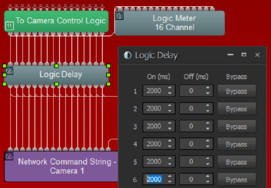
If no microphone is active, the 'Reset to Main Camera' NAND Gate in the logic circuit will trigger the room camera for the default room view.
Camera Control With Control System
We recommend connecting all cameras to the control system and providing one serial or telnet connection from the DSP to the control system. Appropriate command strings as programmed in the control system should be entered in the Command String block(s).
Camera Control with Direct Connection to Cameras
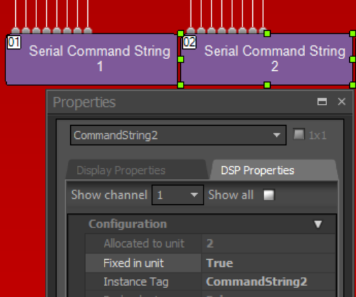
There is 1 serial port available on each Audia, Nexia, or TesiraFORTE device and 2 serial ports on each TesiraSERVER-IO device, allowing a direct connection for 1 or 2 cameras. With a direct connection, the serial command string block needs to be assigned to the unit where the camera its controlling is connected.
For example, if Serial Command String 1 is for Camera 1 connected to Unit 1, and Serial Command String 2 is for Camera 2 Connected to Unit 2, the Command String blocks need to be fixed into Unit 1 and Unit 2 respectively via the property sheet.
Tesira Design Template
Please check out our System Design Template - Conference room with AEC and automatic camera control for an example of camera control with a Tesira DSP.