Generating a clock signal for logic circuits
In some applications, the desired functionality calls for a pulsing logic signal to trigger an action, the most common being a blinking LED. The best way to achieve this is by making a "clock" circuit using logic blocks. In Audia and Nexia, there are two ways to create a clock signal. This article explains both methods, and discusses the pros and cons of each method.
Clock signal with logic blocks
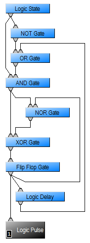 Build a logic circuit as shown on the right. When the Logic State is turned on, the Flip-Flop gate at the bottom will output a pulsing signal. Both the On time and the Off time can be adjusted in the Logic Delay block.
Pros: This circuit uses only logic, so there is no DSP load. Also, the Logic Delay allows controlling both the On and Off times independently so we can have a short pulse followed by a long pause.
Cons: Depending on the complexity of the configuration file, and how much other logic and/or external control is taking place on the system, the timing might not be precise using this method. This is because the system's top priority is to process audio signals, and logic signals are processed at a lower priority.
Clock signal with a tone generator
- Using a tone generator, a high pass filter, a ducker and a signal present meter, build the circuit shown below:
- Load the file to your system.
- Double-click on the Tone Generator block and make the following adjustments:
- Set the generator to Sweep.
- Un-mute and set the generator's level to 0dB.
- Set the Start Frequency to 1000Hz and the Stop Frequency to 2000Hz.
- Set the Frequency Increments to 1 Octave.
- Set the Increment Time to the desired clock pulse speed, in milliseconds.
- Double-click on the High Pass filter and make the following adjustments:
- Set the filter to BW24.
- Set the cutoff frequency to 1500Hz.
- Double-click on the Ducker and the Signal Present Meter and make the following adjustments:
- Enable the Logic Output of the Ducker.
- Turn on the Mix Sense button.
- Increase the threshold in the Ducker until the Signal Present Meter shows a pulsing signal.
Pros: This clock is very stable, since it's being generated by an audio signal rather than logic.
Cons: It consumes some DSP resources that might not be available.