Signal monitoring techniques
This article describes Audio and Logic signal monitoring techniques in Audia and Nexia software.
Sometimes, it is required to monitor the integrity of the signal path within a system so that an alarm is raised should there be a failure. Below are a few techniques that can be implemented to this purpose, when using Biamp Audia or Nexia products. In these, Audia or Nexia will inform a control system of a problem (or that the problem has been resolved), and it will be the control system’s responsibility to act upon that message.
Signal present monitoring
Example 1
The following circuit allows monitoring of a steady input tone (also known as Pilot tone). If the tone falls below a set threshold; a logic event is triggered. This event can be a Preset, a Logic Box or VCB output, an ASCII string sent via the serial port, or a combination of any of the above. If the tone is restored and goes back above the threshold, a second event can be triggered. This second event could be used to reset and restore any alarm that may have been raised previously.
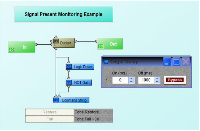
Figure 1– Signal present logic circuit
The circuit above works as follows:
For as long as the tone is above the Ducker threshold, the Logic Node will remain Hi (1) (quiescent state). As soon as the tone falls below the threshold, the logic node will go Lo (0). If it remains so for a period longer than the Off time of the Logic Delay, this state will be reflected on the Logic Delay output node. In turn, this state is reversed by the NOT gate, creating a Lo to Hi transition which is sensed by the Command String thus triggering the ‘Tone Fail’ string out of the RS232 port. If the Pilot Tone goes back above threshold; the Ducker’s logic output node will go from Lo to Hi, hence triggering the “Tone Restored” string.
For this circuit to work, the Ducker’s threshold needs to be set to a level below that of the incoming tone, but high enough so a failure of that tone will be easily detected. Ducker’s Logic Out needs to be enabled. Off time on Logic Delay determines how soon the system will react when the tone falls below threshold, and can be seen as a buffer to avoid false triggering.
This circuit can also be used for other purposes. For example, where remote EXPI and EXPO units are used, the tone can be looped back from an EXPO output onto an EXPI input, thus used to monitor the operation of these two units.
Example 2
Sometimes, a recorded message stored in an external solid state device is used as part of the system. If this message needs to be monitored for availability, it’ll be set to play constantly and its presence sensed by Audia. As the incoming signal from a typical message isn’t a steady tone and contains gaps, the previous example circuit will not work reliably enough. The circuit in figure 2 may provide a better option.
As with the first example circuit, an event is triggered if the incoming signal is no longer present. A second event can be triggered if the incoming signal comes back.
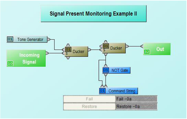
Figure 2 – Signal present II logic circuit
The circuit above works as follows:
For as long as the incoming signal (pre-recorded message) stays above the first Ducker’s threshold, the Tone is attenuated. As the second Ducker senses no signal above its threshold, its logic output node is Lo (quiescent state). If the incoming signal falls below threshold, then the Tone is no longer attenuated. It then exceeds the second Ducker’s threshold, sending its logic output node to Hi, and so triggering the “Fail” string. If the incoming signal comes back, it’ll attenuate the Tone, and hence send the second Ducker’s logic output node to Lo. This state will be reversed by the NOT gate, and therefore trigger the “Restore” string.
First Ducker’s Release Time may need to be adjusted so as to ensure that gaps in the recorded message don’t trigger false alarms. Second Ducker’s Logic Out needs to be enabled.
Oftentimes the Tone generator can be replaced by the Pilot tone, as this is usually present within the system already.
Logic monitoring
Logic loop
A common request is to regularly and automatically update the control system with a message; to ensure the DSP unit is powered on. If the message isn’t received within a certain period, the control system will assume the DSP unit is down.
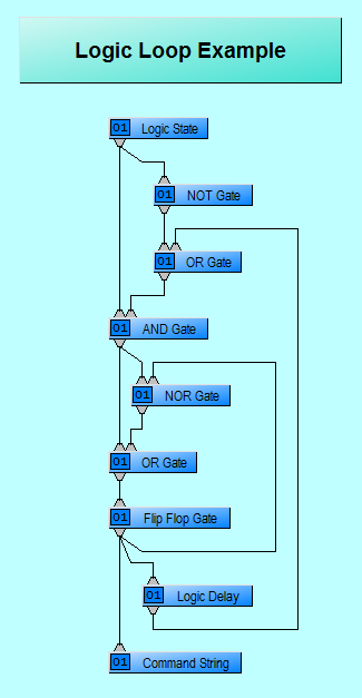
Figure 3 – Logic Loop circuit
The example circuit above will cycle when the Logic State is On, periodically triggering a Command String.
Logic Delay’s On Time determines how long the Flip Flop Gate logic output node remains Hi; its Off time how long the Flip Flop Gate logic output node remains Lo. For example, if we want the string to be triggered every 5 seconds, we will set the On time to 10ms (enough to trigger the Command String), and the Off time to 5000ms.
To allow for easier maintenance in the system, the logic sequence can be stopped temporarily by switching the Logic State off. Switching it back on restarts the cycle.
Multi-unit logic loop
The circuit in the example above can also be used as the basis for two (or more) units monitoring each other. In such a case, a logic pulse is generated by one unit and monitored by the other unit and vice versa. If the pulse on one unit stops, the other unit will trigger an event (preset, string or Logic Box output, etc), to indicate the failure of the first unit. If the second unit fails, then the first unit will raise the alarm.
NPS-1 monitoring
The Network Paging Station has two logic nodes to aid with monitoring; CN and MG. The CN node will remain Hi for as long as any Network Paging Station unit associated with the block is connected to and CobraNet is present. As with examples above, this can be used to trigger an event when CobraNet is no longer present, and to trigger another event when communication is re-established as shown in figure 4.
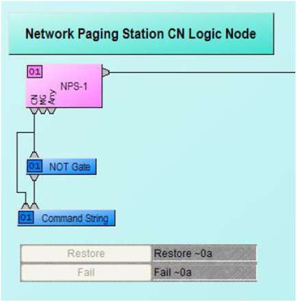
Figure 4 – Network Paging Station logic circuit
If more than one Network Paging Station unit is associated with the block, the CN node will remain Hi as long as at least one unit is connected.
The MG node will stay Hi for as long as all Network Paging Station units associated with the block are deemed to have their capsule intact. If any of their capsules is measured as faulty, then the MG node will go Lo. This feature allows monitoring the functionality of the actual microphone capsule.