AEC in Audia and Nexia
This article summarizes basic concepts of Acoustic Echo Cancellation (AEC) to better introduce design guidelines for Biamp's AEC technology, as used in AudiaFLEX AEC-2HD cards, as well as Nexia® TC and Nexia® VC products.
We focus on simple troubleshooting and system optimization techniques, with in depth information about the AEC process.
This document should provide useful information to system designers and installers on how to maximize the performance of AEC designs.
AEC video tutorial
Watch the video for a short introduction to AEC implementation.
Setting up an AEC system
Each installation is unique, therefore each system will require unique settings and adjustments. Nevertheless, the following steps will provide good performance results for most typical AEC system installations:
- Turn down your power amplifiers.
- Adjust your microphone input gains such that your RMS meters are hitting approximately 0dB when someone is talking in front of them.
- Adjust your gain structure throughout the entire system to have a nominal 0dB.
- Then slowly bring up the levels of your amplifiers until you have sufficient signal.
- Do a test call and then adjust microphone levels if required.
- Check the Echo Return Loss (ERL) Value in the Advanced parameters on each AEC input. For best performance results, ERL value shall be between 0 and –16dBu while the far end talks. If the value is positive, it indicates that amplifier volumes are too high or microphones are too close to the speaker.
- Once operational, make level changes as required but do not change the volume of the amplifier.
Troubleshooting AEC systems
The following simple troubleshooting techniques should be used whenever required.
Residual echo
- Make sure all units are running on the latest firmware.
- Verify that routing to the AEC reference is correct
- Meter the signal feeding the AEC reference and make sure it is within the recommended range (-3dBu to +3dBu).
- Adjust NLP settings from soft to medium. If echo is still being heard, switch to aggressive.
Automixer is not gating ON/OFF properly
- This symptom indicates that the Adaptive Threshold Sensing (ATS) is not working properly. Make sure that all microphone inputs have nominal 0dB gain when talking into the microphone.
- The addition of a Leveler and Level Control in combination with proper microphone input gain is an efficient method of getting a signal to consistently trigger the gate of the Automixer.
Positive ERL values
There is probably too much acoustic coupling between the microphone and the speaker as explained in the AEC basics section. Possible causes may be:
- Amplifier volume is too high
- Poor microphone/speaker placement
- Input gain of the microphone is too high
- Not enough signal being fed to the AEC reference
- Gain structure is not optimized
|
ERL Values |
Most probable cause |
System performance |
Solution |
|
Positive Values: BAD |
Volume of amplifier is too high Problematic microphone/ speaker placement Far end signal to the AEC reference is too low |
Average or poor performance results AEC algorithm may not be able to converge properly Residual echo may be heard |
Lower the volume of the amplifier Adjust input gain Increase signal fed to AEC reference to artificially lower the ERL |
|
Negative Values: ERL between GOOD |
Acoustic echo loss between the loudspeaker and the microphone |
Best performance results |
No modifications required |
|
Extreme Negative Values: ERL between -30dB and -16dB BAD |
Microphone gain is too low or the AEC Reference signal is too high Improper gain structure |
Average or possibly poor performance results Residual echo is being heard |
Check gain structure Increase microphone input gain Decrease signal fed to the AEC reference |
Room design guidelines for AEC
Direct loudspeaker to microphone coupling should be avoided for best system performance. This general design guideline is no different than a typical installation where the designer will try to optimize gain before feedback.
Ceiling Microphones
While commonly used, ceiling mics are problematic for the following reasons:
- They present the worst conditions for acoustic coupling between the microphone and the speaker, as both may be physically mounted in the same surface.
- ERL values will very likely be positive since acoustic echo loss between the loudspeaker and microphone is minimal - the mics are very close to the speakers.
- Poor voice pickup due to the distance from and off-axis position relative to the participant's mouths.
- Poor gain before feedback due to low voice volume relative to ambient room noise - due to distance from the mic.
- Poor voice pickup due to low voice volume relative to ambient room noise - due to distance from the mic.
- Poor Signal-to-Noise Ratio (SNR) due to low voice volume relative to ambient room noise - due to distance from the mic.
For all these reasons, and from our years of experience with AEC systems, Biamp Systems does not recommend using ceiling microphones if it is practical to use individual mics for participants. However we recognize the aestheic bias toward micing from above and will work to help get the best results possible with all configurations. Understanding the inherent issues and common problems faced with these installations is an important step for every designer/installer.
Microphone and Speaker Placement
Placing the mic as close as possible to the person speaking will improve your system's performance.
Avoid positioning your microphones and loud speakers close to one another to minimize the direct coupling between the two. At a minimum, placing them into seperate ceiling tiles to increase isolation is important.
Use appropriate placement of microphones to maximize signal to noise performance. If possible position mics so the coverage pattern is directed away from air handling noise, machinery noise, traffic noise, or other ambient noise.
Microphone choices include ceiling, boundary, gooseneck, DSP based microphone arrays. Try to find the best solution for the acoustic challenge at hand. Aesthetics are important, but intelligibility and a great sounding system are important as well.
Room Acoustics
Acoustic treatment matters! Whether you are using AEC or not, the rules of physics still apply. An AEC system is not a solution to improve intelligibility in a highly reverberant and noisy environment. Rooms that already yield poor intelligibility make for terrible conferencing rooms. Correcting an acoustical problem is best solved using acoustical treatment.
Purpose built acoustic treatments are the first line of defense. Surfaces such as carpets, acoustic tiles, and bookshelves can provide surface area to absorb, dampen or at least attenuate acoustic echo. On the other hand, highly reflective surfaces (glass, bricks, etc.) will tend to reflect most of the acoustic signal and create reverberation that may exceed the tail length limit of the AEC algorithm.
Understanding AEC
Acoustic echo
Acoustic echo is caused by acoustic coupling between a microphone and a loudspeaker in remote conferencing applications.
- The Far End signal is amplified and then reinforced by loudspeakers at the Near End.
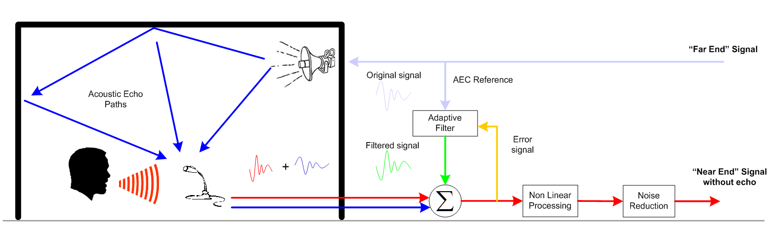
- The direct sound (line of sight) from the speaker is picked up by the Near End microphone and sent back to the Far End. Additionally, the Near End speaker's sound gets reflected off tabletops, walls, ceiling, floors and people before getting picked up by the Near End microphone and transmitted back to the Far End (remote site). The sum of these returning signals is the acoustic echo.
- Acoustic echo is perceived at the Far End by the Far End talker, who hears his original signal returned a few hundred milliseconds after speaking.
The following diagram illustrates the concept of acoustic echo.
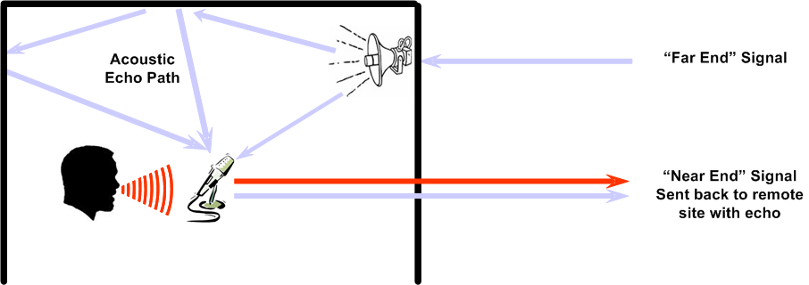
Acoustic echo path
An acoustic echo path is a reflection path between the loudspeaker and microphone causing echo at the far end. (See the diagram above.) As sound bounces off of reflective surfaces within the space, a number of echo paths are defined. The shortest paths are the loudest (if all surface materials are equally reflective) and most prominent.
AEC reference
The AEC reference is the signal that needs to be removed to prevent echo. In other words, it is the far end signal (Codec + Telco) but may also include local sources, such as DVD or CD player that you do not want to transmit back to the remote site.
Referring to the diagram below, the AEC reference is used to model the signal that needs to be removed from the microphone input channel. Based upon this model, an adaptive filter is created and continuously updated.
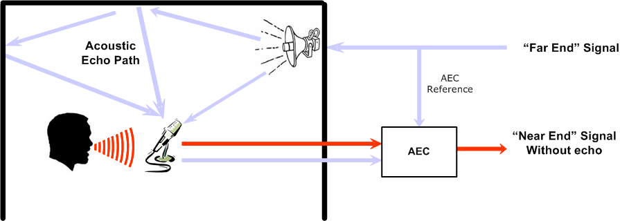
AEC algorithm
By continuously monitoring differences in samples between the original "Far End" source signal and the local "Near End" microphone input, the AEC algorithm calculates filters to eliminate the echo. The AEC algorithm determines the acoustic echo components added between the loudspeaker and the microphone and applies adaptive acoustic filters to remove both the original "Far End" signal and its artifacts from the return leg.
Complexities of Acoustic Echo Cancellation
- First of all, the acoustic echo signal picked up by the microphone is different from the AEC reference. It has been amplified and played back in an unknown acoustic environment where acoustic reflections have further modified the signal.
- An adaptive filter performs what is called “system identification” of the acoustic echo paths, also referred as 'training of the filter'. This is the process of modeling an out-of-polarity signal intended to cancel out the far end signal picked up by the microphone. The adaptive filter design is where most of the AEC complexity lies. Adaptive filters need to correct for not only the direct path from the speaker, but also reflection paths from surfaces within the acoustic space.
- Finally, acoustics of a room may be constantly changing (a wireless microphone being moved, people coming and leaving the room, etc.) and the AEC algorithm needs to adapt to those changes by updating filter parameters accordingly.
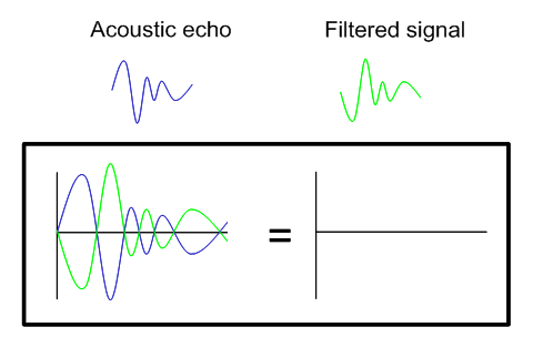
The Echo cancellation process
- The AEC reference signal is initially sampled by an adaptive filter.
- The parameters of the adaptive filter are adjusted during convergence.
- The resulting filtered signal is an out of polarity model of the acoustic echo paths.
- Echo is removed when the filtered signal is summed to the AEC input microphone signal.
- In the presence of any residual echo, Non-Linear Processing is applied on the signal as needed to suppress it.
- Finally, noise reduction may remove up to 15dB of static background noise picked up by the microphone.
Features of the Biamp AEC card
Biamp's AEC technology in AudiaFLEX AEC-2HD cards, Nexia TC, and Nexia VC is referred to as a wideband echo canceller. It operates from 20Hz to 20 kHz, even in double talk conditions.
Because wideband AEC algorithms are DSP resource intensive, they require dedicated DSP processing on a per channel basis. In other words, DSP processing power is not shared among AEC inputs and it does not consume normal AudiaFlex DSP resources. This specific aspect of Biamp Systems’ AEC products allows each microphone to converge independently with optimized filter parameters and, consequently, achieve better results than global AEC systems (a single AEC channel for multiple microphones).
Common AEC terms
- Tail length
- Tail length refers to the maximum echo time delay that will be removed by the AEC algorithm. The tail length of Biamp's AEC technology is up to 300ms.
- Convergence rate / Loss of convergence
- Convergence refers to the adaptation process inside the AEC algorithm. The convergence rate indicates how quickly the AEC algorithm models the room and adapts to echo path changes. An algorithm 'converges' when it efficiently modifies the parameters of the adaptive filter and echo is removed. Loss of convergence occurs when the AEC algorithm cannot track acoustic echo path changes resulting in echo being heard by the far end. Loss of convergence is most commonly caused by incorrect gain structure.
- Residual echo
- Residual acoustic echo signal that was not removed by the AEC algorithm.
- Double talk
- This occurs when speech is generated on both ends of the line. It is the most demanding state for the AEC algorithm.
- Far end
- The side on which the AEC algorithm does not operate. The far end room needs its own AEC solution to stop us hearing echo at the near end.
- Near end
- It refers to the side upon which the canceler is designed to operate. Remember that while the AEC hardware operates at the near end, only the far end benefits from acoustic echo cancelation. This explains why AEC systems are required on both ends for a complete conferencing solution.
AEC input block options
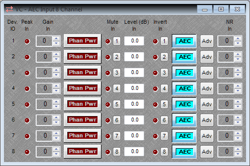
- Dev IO
- Device input channel shows the channel number for this AEC input block. This will show ?? until you compile the design, then it will change to reflect the corresponding input number.
- Peak In
- If you are clipping the input to the mic pre-amp the Peak Input light will flicker, flash, or steadily light up. If this is happening you need to reduce the gain level. Clipping will result in unacceptable distortion in the system.
- Gain In
- Gain In adjusts the sensitivity of the microphone in 6dB steps. This is achieved by adjusting the voltage supplied by a high-quality, professional analog pre-amp in the AEC card. 0dB is the gain setting for a line level input device, microphones will need additional gain applied. The range is from 0dB to +66dB in 6dB steps.
- Phantom Power (Phan Pwr)
- Phantom power is 48vdc power applied to the microphone input. It is used to supply bias power to a condenser mic. It is not needed for dynamic mics or line level sources and may damage them if applied.
- Mute In
- Mutes the input.
- Level (dB) In
- This allows digital gain adjustment after the mic pre-amp to fine tune the input level. The range is -100dB to +12dB.
- Invert In
- Inverts the polarity of the input signal. Also known as a "phase reverse" or "phase flip" switch.
- AEC
- Turns the AEC adaptive filter on or off. This should be left off for unused channels or for channels not needing AEC.
- Adv
- Opens the Advanced settings window for this input channel.
- NR In
- This is where you'll adjust Noise Reduction (NR) input level. Automatically removes steady state background noise (e.g. air handling, projector fan, etc.) from the AEC input signal. Noise reduction is a useful tool to improve the audio quality of the signal transmitted back to the remote site. 0dB equates to the noise reduction being off, the first step (the minimum) is 6dB, noise reduction is adjustable from 6dB to 15dB of reduction. Start at 6dB and adjust this filter upwards until the background noise is filtered to an acceptible level.
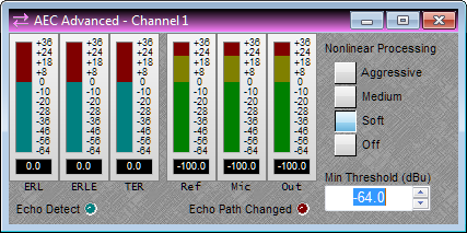
Advanced AEC settings
IMPORTANT: The Advanced AEC settings need to be checked and adjusted for each mic in the system.
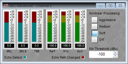
- Echo Return Loss (ERL)
- Amount of acoustic echo loss (in dB) between the AEC reference and the microphone. Negative values indicate a loss and are desired for best performance. A positive value can indicate the mic input gain is too low or the speakers are too loud. A target area of 0dB to -16dB is optimal.
- Echo Return Loss Enhancement (ERLE)
- Amount of echo attenuation or reduction (in dB) introduced by the AEC algorithm.
- Total Echo Reduction (TER)
- It represents the sum of the ERL + ERLE and indicates the total echo reduction that was introduced by the room acoustics (ERL), the AEC algorithm, and Non Linear Processing (ERLE).
- Non Linear Processing (NLP)
- NLP is equivalent to a sophisticated ducking technology used to suppress any residual echo that the AEC algorithm did not cancel. Three NLP settings are currently available: Soft (set by default), Medium and Aggressive.
- Reference (Ref)
- Reference shows the level of the AEC Reference signal that the AEC algorithm is comparing to what this microphone is hearing.
- Microphone (Mic)
- Mic shows the input level of the currently selected microphone. This level should be at about 0dB for normal speaking levels in the space.
- Output (Out)
- Out shows the post-AEC gain for this microphone channel.
Designing systems with AEC
A successful design usually involves a combination of good Audia/Nexia programming design skills as well as good overall system design skills (including microphone placement, speaker placement, room acoustics, etc). Although an open architecture DSP like AudiaFlex can help overcome some problems, the best designed and performing systems take all of these elements into consideration.
There are many different ways to design AEC systems and the following design guidelines are just recommendations for best results. The only constant design consideration that applies to ALL systems without exception is maintaining proper Gain Structure. AEC systems will perform best with unity gain (0dB) throughout your entire DSP chain, so always keep in mind to set a proper gain structure.
DSP programming guidelines
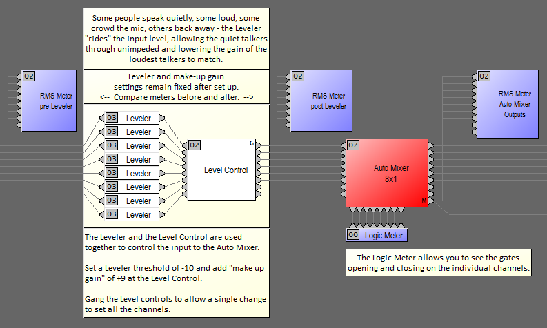
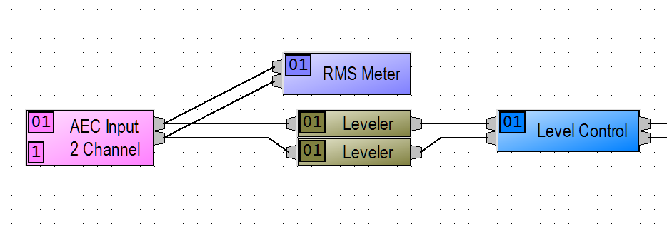
The following section highlights programming guidelines for AudiaFlex platforms fitted with AEC-2HD cards. Click on this layout image to see design details.
The front end design of an AEC input would typically include RMS Meter(s), Parametric EQ(s) or filters if necessary, and Leveler(s) to prevent excessive level changes.
A short note about the Leveler block. The Leveler is an automatic gain control, effectively functioning as a 10:1 compressor, affecting long-term average levels. The threshold setting is the level at which the leveler begins to act upon the signal - if the threshold is set to 0dB, any sound louder than 0dB entering the leveler will be attenuated at a ratio of 10:1, so a +10dB signal coming in would be a +1dB signal going out. The response time controls how quickly the leveler will respond to a signal above threshold. Settings in the 1000ms to 2000ms range are common. A compressor differs from a leveler in the duration of the gain reduction applied, compressors and limiters are designed to handle short-term signal dynamics, or peaks.
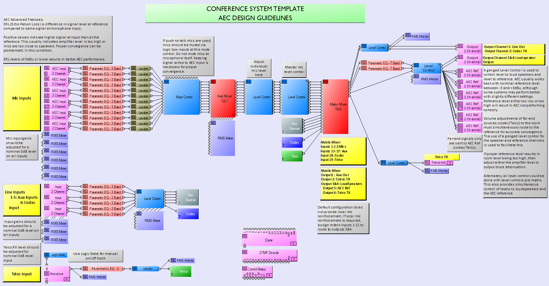
Microphone inputs
- Always meter your inputs (whether they are AEC inputs or not).
- Keep unity gain structure across the entire DSP chain (inputs to outputs).

Within the AEC Input block, click on the Adv toggle button to access Advanced Features of the AEC algorithm. (Remember that settings are on a per channel basis and need to be updated on all inputs for consistent results.)
This dialog box allows you to monitor ERL, ERLE and TER values as well as the AEC reference signal (Ref), and signals at the AEC input block (Mic = Pre AEC and Out = Post AEC). Nonlinear Processing settings for addressing late echo issues are modified here.
See the table in the section "Troubleshooting AEC Systems" which summarizes the influence of ERL values on the system performance.
Line inputs
Set all line input gains for nominal 0dBu reading on an RMS Meter.
The front end of auxiliary and codec inputs would typically include a Leveler (similar to a 10:1 compressor but working by scaling, rather than compressing, the signal) and Level Control blocks. For a larger number of mics the Automixer should be used instead of the Level Control block. If the situation requires it you may also find a need for Parametric EQ or High Pass Filters.
Note: Some video codecs may have a built-in AEC feature. Make sure to disable the AEC inside the codec for best results.
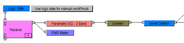
Telephone inputs
The 'Far end' signal typically comes from the phone line or video codec in a conference system.
Remember to meter your input signal and adjust gain for nominal 0dBu reading on an RMS Meter.
A Parametric EQ may help improve the poor audio quality of the typical telephone signal and a Leveler will prevent excessive level changes heard from different calling sites.
Note: A logic state is an efficient way to manually control the Hook State (HS) of the receive block (On or Off Hook).
Muting of microphones
Muting of a microphone could be done of two ways, internally (via contact closures on a Logic Box, control processor, etc.) or externally (at the microphone, in the case of push to talk microphones).
Internal muting
If muting is done after the AEC input (i.e. inside the DSP), it will not compromise the convergence rate of the AEC algorithm as the adaptive filter will continuously be 'trained' whether the microphone is muted or not.
Below is a typical design to internally mute microphones, with contact closures on a Voltage Control Box.

External muting
If muting is done at the microphone, a minimum threshold value will have to be set in the Advance parameters dialog box of each microphone input, such that any input signal below the set threshold value will freeze the AEC algorithm adaptive filter settings in their last state. Using this method will prevent the algorithm from completely re-converging once the signal is un-muted.
The minimum threshold value should be set slightly higher than the system noise floor (when the microphone is muted). Remember that settings are made on a per channel basis and will need to be updated on all channels for consistent performance.
Auto Mixer
An Automixer is strongly recommended on all AEC microphone inputs for the following reasons:
- Automatic system gain adjustments are made based on the Number of Open Microphones (NOM)
- Improves Signal-to-Noise Ratio (SNR) by keeping unused microphones gated off
- Eases the complex work of the AEC algorithm by gating unused microphone channels
If local speech reinforcement is not a requirement, the mix output of the Automixer will be sufficient for your application.
On the other hand, if local speech reinforcement is required, we recommend using the direct outputs of the Automixer for a mix minus design on multiple loudspeaker zones. It will efficiently optimize the gain of the system before feedback.
Note: RMS meters on the outputs of the Automixer are a useful tool for checking whether a microphone gate is on or off.
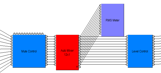
Level Control
The optimal location for input level change is after the Automixer and before the Matrix mixer.
If level control is modified before the Automixer, it may affect the Adaptive Threshold Sensing (ATS) of the Automixer, that is, it will alter how the automixer's gates open and close.
We generally recommend restricting the range of the user-level control to ensure that no major level changes will affect the AEC algorithm performance.
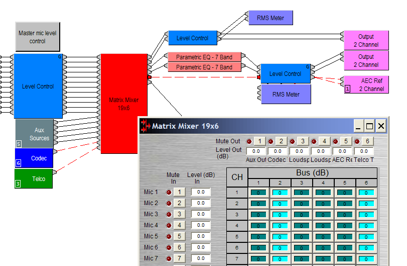
Matrix Mixer
While setting cross points inside the matrix mixer; use the signal path identifier to check whether routing is correct or not. To enable the signal path identifier, right click on a connection line and select “Persistent Signal Path Identifier” > “Normal”.
Signals that you do not want to transmit back to the far end are routed to the AEC reference, these will be items such as:
- Far end signal from the Telco input.
- Far end signal from the Video codec.
- Locally reinforced auxiliary sources, if any.
Incorrect AEC reference routing is the most common mistake seen by the technical support team. Make sure to double check the routing with the signal path identifier to prevent un-necessary troubleshooting.
Output level control for sound reinforcement
Level control for the sound reinforcement signal needs to be “in synch” with the level control to the AEC reference. Mirroring any level changes made to the sound reinforcement signal to the AEC reference will greatly improve convergence rate of the AEC algorithm. Ganging a level control is an efficient way to achieve this.
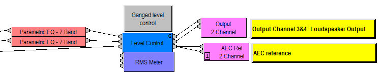
AEC reference
The AEC reference should appear at the output end of the system. For best system performance, the AEC reference level reading on a RMS Meter should be between -3dBu and +3dBu. We generally do not recommend muting or changing routing of the far end signal to the reference in the middle of a call.