Replacing fans on an AudiaFLEX
This article explains how to replace the fans in an AudiaFLEX. The AudiaFLEX has either one or two fans, depending on its configuration. The AudiaFLEX NC (No CobraNet) has a single fan, located on the right side of the chassis (when viewed from the front). The AudiaFLEX CM (with CobraNet Module) has two fans: a chassis fan (same as the NC), as well as a CobraNet fan that is internal to the unit.
The fans should be replaced if it makes excessive noise (especially grinding or groaning noises) or if it doesn't spin at all when the unit is powered on. Note that AudiaFLEX fans are variable-speed and therefore they may not spin at all if the temperature is low enough. However, they should always spin briefly right after the unit is powered on.
Replacement fans can be obtained from Biamp Systems, either as a warranty item or a spare part order. However, there are several different fans available, depending on when the AudiaFLEX was manufactured. Please take note of the serial number of the AudiaFLEX and call Biamp's Service department to ensure you receive the correct fan for your AudiaFLEX.
Required Tools
The following items are required to replace a Audia fan:
- #1 Phillips screwdriver
- #2 Phillips screwdriver
- Replacement Fan(s) (call Biamp Service department for correct part number)
- Two 6-32x3/4 screws with nylon locking nuts:
- 6-32x3/4 screw part number is 525.0016.900
- Nylon locking nut part number is 535.8003.900
Step by step
Follow the steps below to replace the fan(s). Click on any of the images to see a full-size version of the photo.
Removing the cover
- Unplug power to the AudiaFLEX.
- Remove the AudiaFLEX from its rack or enclosure, if necessary.
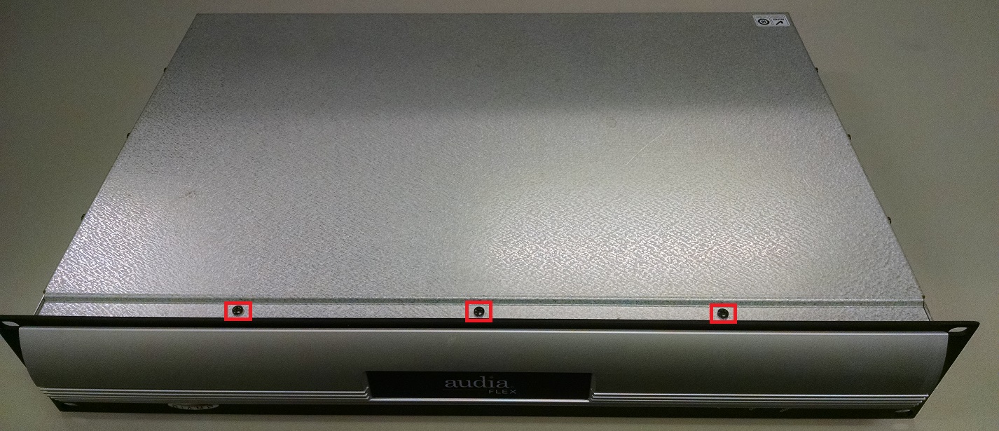
- Remove the three screws from top of the chassis.

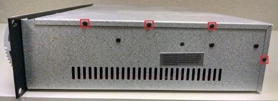
- Remove the four screws from each side of the chassis. Note that the side opposite of where the fan is located has some screws that do not need to be removed.
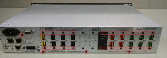
- Remove the three screws along the bottom edge of the rear panel. Remove the screw between the power jack and the RS232 connector. Remove the two screws above and below each pair of I/O card connectors. Any card slots that are empty do not need to have their screws removed from the blank panels.
- Remove the top cover by pushing it back first, and then lifting it off.


Replacing the chassis fan
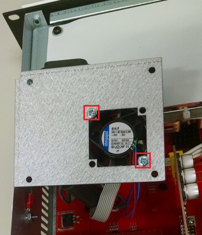
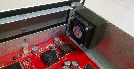
- The fan has a 2-conductor wire that connects to the main board. Note the orientation of this connector so that the new fan's connector can be installed in the same orientation. The correct orientation might be different than the photo below. Disconnect the fan from its connector on the board.
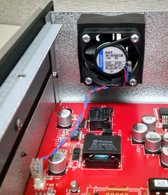
- Remove the old fan by removing the four screws holding the fan in place. Note the orientation of the fan before removing it, so that the replacement fan can be installed in the same orientation.

- Install the new fan using the screws that held the old fan in place. Before installing the new fan, ensure that the opening is clear. Also, please remember that only minimal tightness is needed for fan screws. Over-tightening the screws can cause the fan to make excessive noise.
- Plug the fan connector into the board, where the old fan connector was plugged in. Ensure that the polarity and orientation of the connector is correct. Depending on the age of the unit, the correct orientation may look different than the photos in this article.
- If not replacing any other fans, then replace the top cover and replace all of the screws in the reverse order of how they were removed. Re-install the AudiaFLEX into its rack or enclosure, if necessary, and re-apply power to it. Confirm that the fan spins normally and doesn't make excessive noise. If it makes excessive noise, you may need to re-open the chassis and loosen the screws that hold the fan to the chassis. In general, AudiaFLEX fans are designed to exhaust air from the unit, so if the fan is sucking air into the unit, then the fan may be installed backwards. (Note that older AudiaFLEX manufactured before April 2012 may use fans that pull air into the unit.)

Replacing the CobraNet Module fan
If your AudiaFLEX has a CobraNet Module installed, follow the instructions below to replace the CobraNet Module fan. CobraNet fans are the same model as the chassis fans, but they have a longer cable to reach the spot on the board where they plug in.
- Make absolutely sure that the power cord is not plugged into this device, and don't attempt to remove the old CobraNet fan for at least 10 minutes after it has been unplugged.. The CobraNet fan is in close proximity to the power connector on the unit, and some residual charge may remain in the unit shortly after it is unplugged.
- Remove the four screws holding the power/fan module to the CobraNet module beneath it.
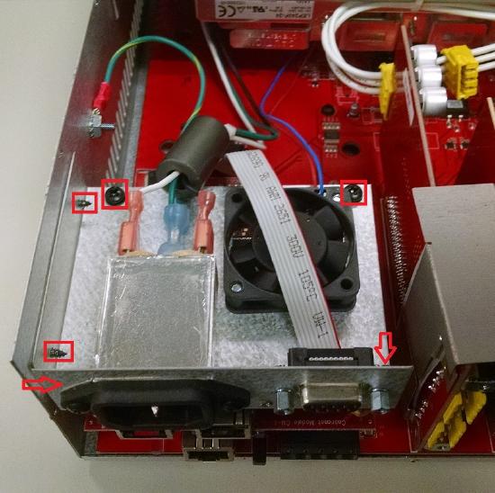
- Remove the two screws holding the power/fan module to the side of the chassis.
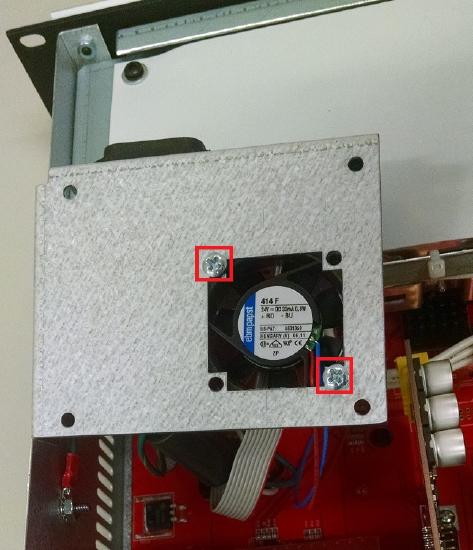
- Lift up the power/fan module and flip it over. Remove the screws holding the fan to the plate. Note the orientation of the fan before removing it, so that the replacement fan can be installed in the same orientation.
- The fan has a 2-conductor wire that connects to the main board. The connection is underneath the power supply. Note the orientation of this connector so that the new fan's connector can be installed in the same orientation. Disconnect the fan from its connector on the board. You may need to temporarily remove some of the I/O cards and/or use long needle-nose pliers to reach the connector underneath the power supply.
- Install the new fan using the included 6-32x3/4 screws and nylon locking nuts. Please remember that only minimal tightness is needed for fan screws. Over-tightening the screws can cause the fan to make excessive noise.
- Plug the fan connector into the board, where the old fan connector was plugged in. Ensure that the polarity and orientation of the connector is correct.
- Place the power/fan module back on top of the CobraNet module, and replace the four screws that hold it to the CobraNet module.
- Replace the two screws that hold the power/fan module to the side of the chassis.
- Replace the top cover and replace all of the screws in the reverse order of how they were removed. Re-install the AudiaFLEX into its rack or enclosure, if necessary, and re-apply power to it.