Developing a custom driver for Powersoft
This tutorial uses the Powersoft Quattrocanali as an example to show the basic principles of configuring a simple driver to turn the device on and off.
Command Example
You can use this example to control other functions in the Powersoft series or devices from other manufacturers. The commands are calculated using the product manual and tools available on the internet. The end product can be added to the functions using Device Editor.
The API manual for the Powersoft Quattrocanali is attached to this article. The table and text below provide specifications for how power commands are formatted.
The Command
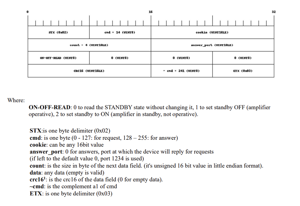
Command Structure Explanation
The command text above can be quite confusing to look at, but separating the segments helps make sense of it.
- STX: The start command
- cmd: This is the command to be sent (see attached manual, 14 controls standby).
- cookie: This is a tag you can enter, It will be included in the answer to the issued command.
- Answer_port: The port at which the reply to the command is sent (if left to 0 the reply is sent to default port 1234).
- count: The size of the data block to be sent, combined is the 4 blocks below (ON-OFF-READ),(0),(0),(0) (in case the value is 4).
- data: The data to be sent.
- crc16: A checksum calculation of the 4 blocks defined by Count (ON-OFF-READ),(0),(0),(0).
- ~cmd: The inverse cmd command.
- ETX: The end command
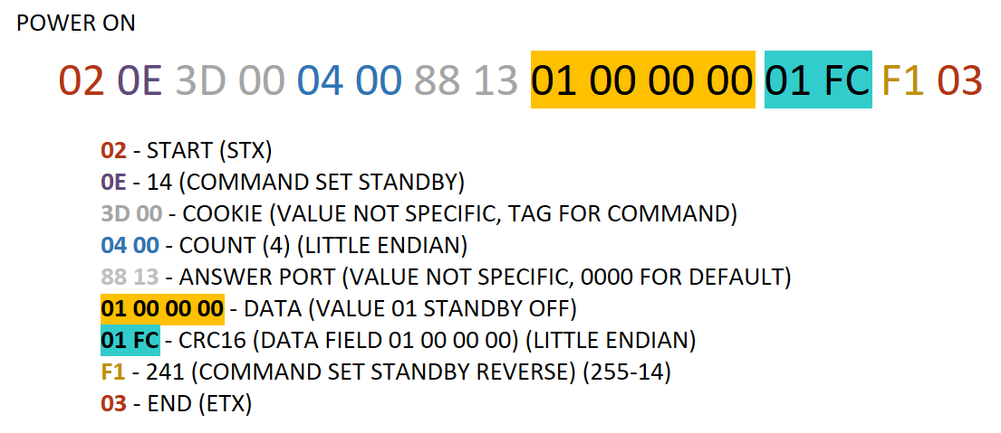
In Hex code
The diagram below shows the command in HEX value. HEX is used for entering the command in Biamp's Device Editor software.
Structuring Commands
Despite the first-glance complexity, sending commands to the Powersoft Quattrocanali is simple. Most fields are static, except the command, command reverse, the command data, and the CRC16 checksum of the command data.
- The command in this example is 14 and the reverse is 255-14 = 241
- Data is 01 00 00 00 for power 0N, and 02 00 00 00 for power OFF.
- The checksum CRC16 is calculated from the data field, and done as CRC16/ARC (remember to use HEX as input, 01000000 = FC01)
- An online calculator can be used to calculate the checksum: Online CRC-8 CRC-16 CRC-32 Calculator (crccalc.com)
- The cookie and answer port lines are irrelevant for this command, and not used in this example.
In this case, where the values for COUNT and CRC16 are presented in little-endian, the two HEX fields are reversed (FC 01 in little-endian is 01 FC).
Entering Commands into Device Editor
The previous section shows you how to break down a command line, going from the manufacturer manual to a valid command entry for a device in Device Editor.
To get the commands into Device Editor:
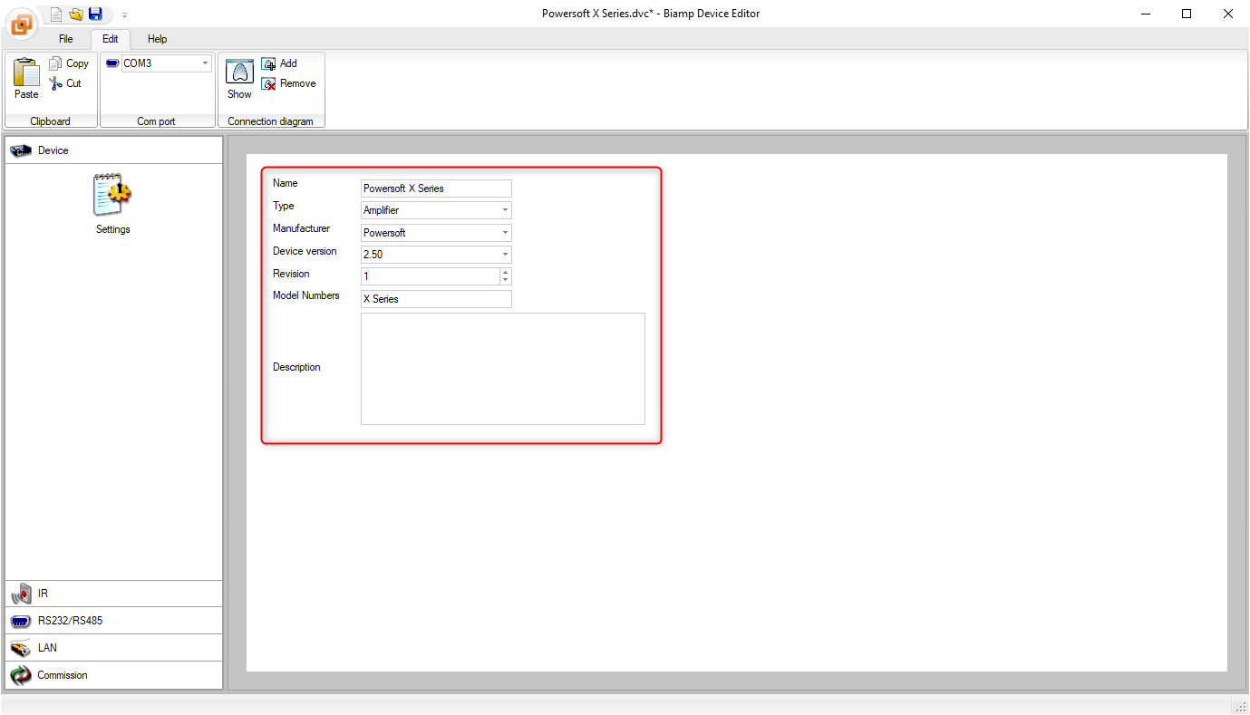
- Open the program, and choose normal mode.
- On the Device tab enter the device information.
- This information is searchable and is the method used to locate the driver in Project Designer device library.
- Go to the LAN tab, select UDP as protocol and port 1234 (standard for Powersoft).
- Under the Power section, enter the command's values from above as HEX code for a Power On/Off sequence.
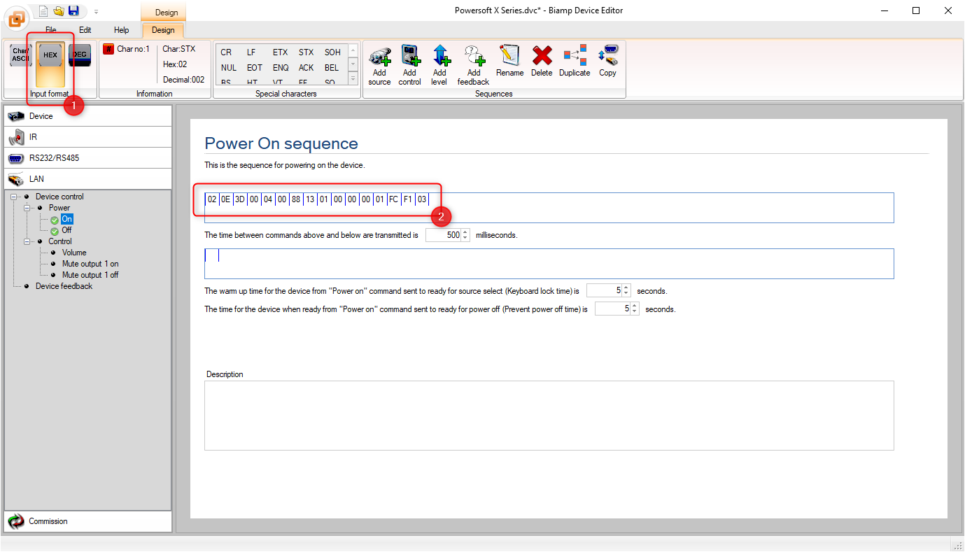
- Save the driver with your desired file name, and it is now ready for you to use in Project Designer.
Please consult the attached manual for details on the programming steps revieiwed in this article.
The Powersoft API uses calculations for levels done by floating values and 16bit CRC. At present, these are not available in Device Editor, which means that Device Editor is not able to control these.