RS-232 Everything you need to know
The RS-232 standard for serial communication was defined back in 1969 by Electronic Industries Alliance (EIA). The idea of the RS-232 standard is to make an identical hardware interface between two units. By now, the RS-232 standard has gone through several upgrades, and the interface has been defined with greater precision and performance has been improved. The last revision of the RS-232 was in 1997. When using RS-232, you can make a point-to-point connection between two units. Both connected units must know the transmission speed, number of data bits, number of stop bits, and the use of
parity. If this is not the case, the units will not be able to communicate.
How and why RS-232 is used
The RS-232 interface is extremely common. The RS-232 interface became popular because it is simple and cheap. It was quickly adopted by the computer industry and was commonly referred to as the “serial port.” The serial port could be used to connect a computer to a modem or other peripheral devices. It was the predecessor of the modern-day USB port. Over the last decade, the use of RS-232 in the computer world has been reduced dramatically in favour
of the USB interface. But the RS-232 still offers an easy, cheap and reliable interface, and is still commonly used in many industries. In the AV industry, the RS-232 interface is still the most common way of controlling AV equipment, such as projectors, video/audio switches and audio amplifiers.
RS-232 Signal
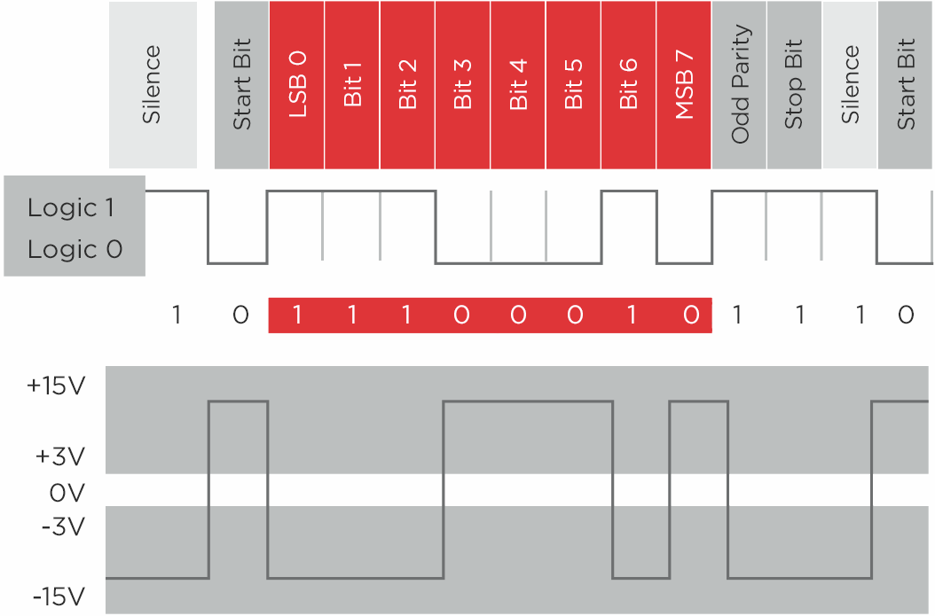
The RS-232 signals are serial data communication. The RS-232 line has two states: either high or low. According to the standard, the high level can range between -15 and -3 V and the low level can range between 3 and 15 V. The voltage level of the RS-232 transmitter significantly impacts the total transmission length of the line, so the closer the line signal is to 15/-15 V the longer the transition cable can be – and the more immunity it will have to external interference.
Below, you see an image that shows the relationship between the data that you send and the
RS-232 line-level.
Line-levels are just one of many aspects used by the RS-232 to transmit data. Characteristics such as speed, parity, and stop bit play important roles as well. The pin out of the 9-pin D-sub connector,
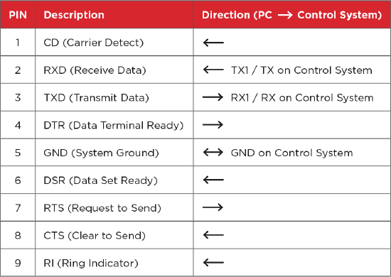
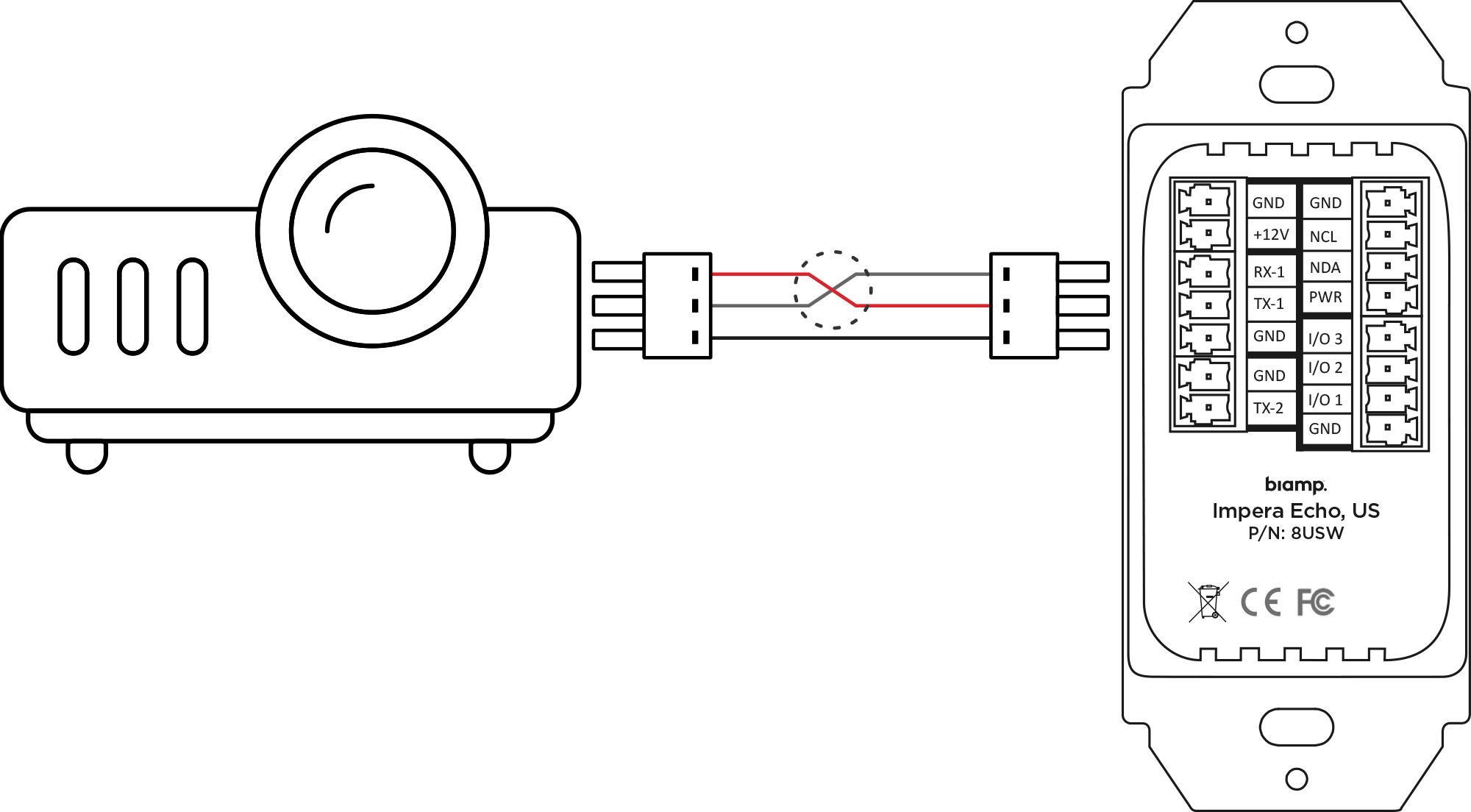
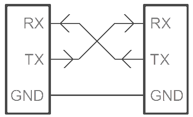
Remember, the importance of crossing Rx and Tx (pin 2 and 3) because the receiver needs to listen on the transmitting part from the counterpart and vice versa.
As shown in the two illustrations:
Speed
This is the speed at which the data is transmitted through the cable. It is essential that the speed you select is the same on both units e.g. the projector and the control system.
Many projectors have a fixed speed and some have 2 or 3 different speeds. If your projector allows you to change the speed setting, we recommend you select the lowest possible speed.
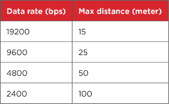
This is because the transmission speed and the maximum cable length are inversely proportional: Lower speeds are more tolerant of external noise and make it possible to use a longer cable.
Below, you see a table that specifies the maximum length of the cables. The cable length is defined in the EIA RS-232C standard, but can be longer or shorter depending on the situation.
Any wire near the RS-232 cable can potentially disrupt communication. However, high voltage wires (from 110 VAC and up) are those most likely to cause problems. If a cooler unit (motor) is at the end of one of these high voltage wires, the risk of disruption further increases. Also, if you are using a projector screen operated by an electric motor, your system will be exposed to more noise because the screen inducts high voltages when starting, stopping and changing direction.
Start bit
The start bit is always sent, and is not a factor you have to consider when creating devices for Biamp Control Systems. The start bit is always only 1 bit long, so not a variable you can change, it’s a part of the RS-232 standard.
Stop bit
The stop bit is the last bit that is sent when sending a byte. The purpose of the stop bit is to inform the receiver that the transmission of this byte is complete. The stop bit and the start bit are always sent.
This means that even if you try to send “nothing,” something will always be sent. Like the speed, both the transmitter and receiver must be set to use the same number of stop bits (1, 1.5, or 2) for each byte.
Parity bit
The parity bit is an error detection mechanism. Electrical interference can corrupt the transmission of data while on its way to the receiver. Fortunately, we can determine if a byte has been accurately transmitted by using the parity bit.
Using the parity will add one bit to the total length of data that is transmitted. As with the transmission speed and the stop bit, use of parity must remain consistent among both transmitter and receiver. There are different ways of detecting errors in a transmission using the parity bit.
The most common method uses the simple logic of even and odd numbers. For example, if the parity is set to ‘even’, the number of bits whose value is ‘1’ is counted. If the total number of ‘1’s in the set is even, then the parity bit is given the binary value ‘0’ and if it is odd, the parity bit will be given the binary value ‘1’. Therefore, for even parity, the total number of ‘1’s in the transmitted data should always be even. If this is not the case, an error has occurred. However, this is not the most reliable method for detecting errors because errors can potentially cancel each other out.
When using parity for validating the integrity of the byte that is transmitted, remember that re-transmitting of the data is not a part of the RS-232 standard and must therefore be handled by the application layer (e.g. control system and projector).