Using an input for a movement sensor (PIR)
You can set one of the inputs on any of the Impera controllers to trigger any action from the activity of the movement sensor.
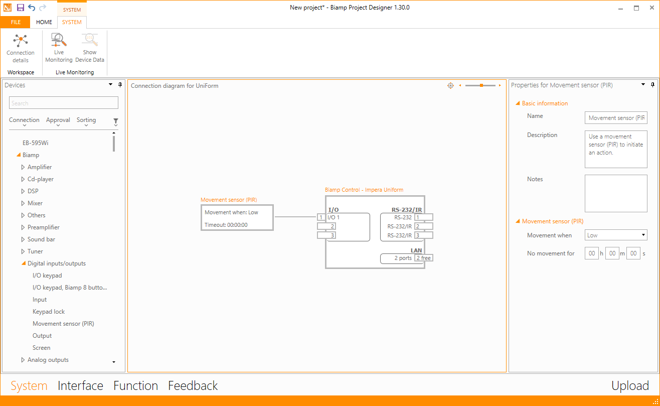
Below is a diagram that shows the wiring to make it work with a normally closed PIR movement sensor.
First, you start in System and insert a Movement sensor (PIR) from the Biamp->Digital inputs/Outputs category.
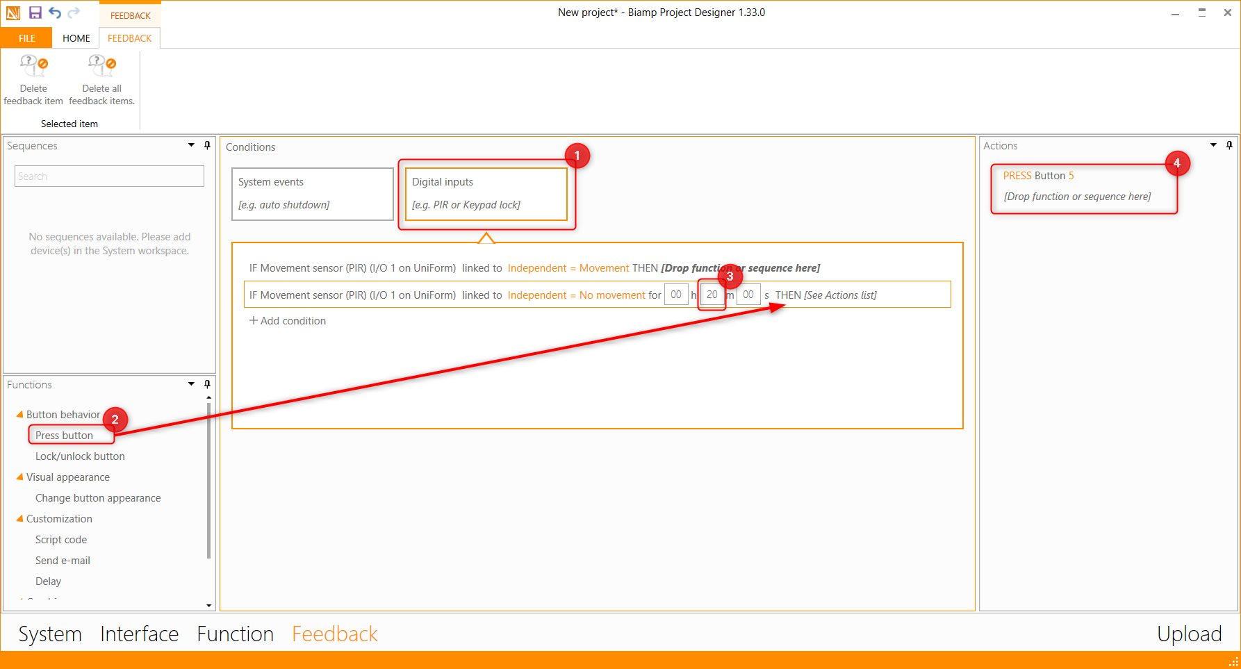
Then you go to Feedback and define the actions you will need the controller to perform when either detecting movement or as often used when no movement is detected for an amount of time!
Steps are as following:
- Select the "Digital inputs" window.
- Drag "Press button" to the line of "No movement", then select the button you wish to press (often the OFF button).
- Set the time for "No movement" (after no movement for X time, the command will be executed).
- See the actions window to verify your steps above.
Refrain from using Sequences and stick to using Press button in order to keep the button states synchronized.
Troubleshooting
Remember that the GPIO input is looking for voltages above or below the following thresholds:
- Input trigger low: < 1VDC
- Input trigger high: > 4VDC
When in doubt, use a multimeter to measure the output of the switch or sensor and document the findings. Then connect the switch or sensor to the GPIO and take the measurements again. In some applications, the sensor output may not pull the circuit down below the 1VDC threshold. If this is the case, a resistor can be added to the circuit in series or parallel with the sensor. Measure and test until expected functionality is achieved.
24VDC is a common sensor logic output used as the 'High' output of sensor; when connected to the GPIO of an Impera controller, the 'Low' output may only pull down to 3VDC. This will not pull down far enough to trigger the 'Low' so applying a 4.7k or 10k ohm resistor to the circuit will change the measured 'High' and 'Low' to operate within the proper range.