Connecting paging and background music inputs to a QtPro system
This article will provide guidance for understanding and making the proper connections to the QtPro Processors for the purposes of integrating a paging or background music signal in conjunction with the sound masking signals.
Each Qt control module features terminal block inputs on the rear of the unit that will accept US Pro Line Level audio signals. The Qt 100 features one auxiliary input while the Qt 300 and Qt 600 each feature two inputs. The input on the Qt100 control module is primarily used for low level background music in quiet environments. The inputs on the Qt300 and Qt600 can be used for both paging and background music.
The input connection is via a 4-pin terminal connector, either balanced, unbalanced or stereo.
Considerations
Before connecting a background music or paging source to your Qt system, there are a few considerations that must be taken into account to ensure proper usage and operation.
Emitter Type
The QtPro System contains two different types of emitters. The Standard Passive Emitter which has a maximum output of 55dba for music and paging, and the Active Emitter, which has wider frequency range and has a maximum output of 74dba for music and paging. Your source type and the environmental use case will determine which type of emitter you will need. For background music, environments with a very low noise floor, such as doctor's offices, law firms, or waiting rooms, can be approached with either type of emitter. If the environment has a higher noise floor and louder levels are needed from the emitter to produce audibly comfortable music, than the Active Emitter must be utilized as it is capable of producing higher levels of sound in the space.
If paging is required, only Active emitters are recommended as they produce a higher level of sound to better allow pages to be heard and understood. Standard emitters do not have enough output to effectively meet the needs of a paging system.
Multiple Inputs
The Qt 100 unit has a single input that cannot be muted by a contact closure. The Qt100 is not compatible with the Active Emitter.
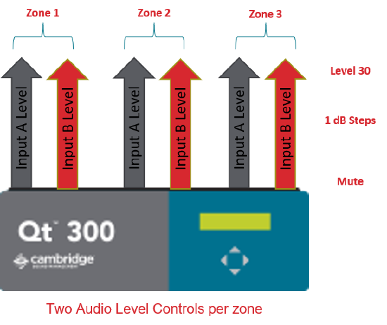
The Qt 300 and 600 each have two inputs labeled Input A and Input B.
These inputs can be configured in a matrix fashion to be directed to any processor output zone with individual level control per zone at 1 db steps.
Note. Each zone on the QtPro control modules contains two physical runs. These runs are internally the same zone and cannot be sent separate sources.
Contact Closures
The QtPro 300 and 600 series control modules have two contact closures. Contact closure A is a global mute and will mute the sound masking signals during an emergency. Contact closure B mutes input B.
Input A is primarily the Paging Input and is not muted upon receipt of a contact closure, so paging signal important messages are allowed to continue. Input B is generally the Music input and is muted by the contact closure B. The sound masking signals are muted using on contact closure A during emergencies.
NOTE: The Qt100 control module does not have contact closure capabilities.
| Input | Intended Source | Muted Upon Contact Closure |
| Input A | Paging | No |
| Input B | Background Music | Yes |
An Important Note on Paging Signals
It is important to pay attention to the control module’s audio input requirements when implementing paging with your sound masking system. All Qt control modules require a dry line-level signal from the paging source. The specification for a nominal pro audio line-level signal is +4 dBu, 1.228 (Vrms), 1.737 (Vpk). However, Qt control modules can handle signals that range from 1/2 to 2 times pro audio line levels. “Dry” emphasizes that the module’s paging inputs are not telephone interfaces and must never see dial tone, ring voltage, battery current, etc.. This means that a typical FXO/FXS output is NOT directly compatible and requires the use of a third-party paging controller.
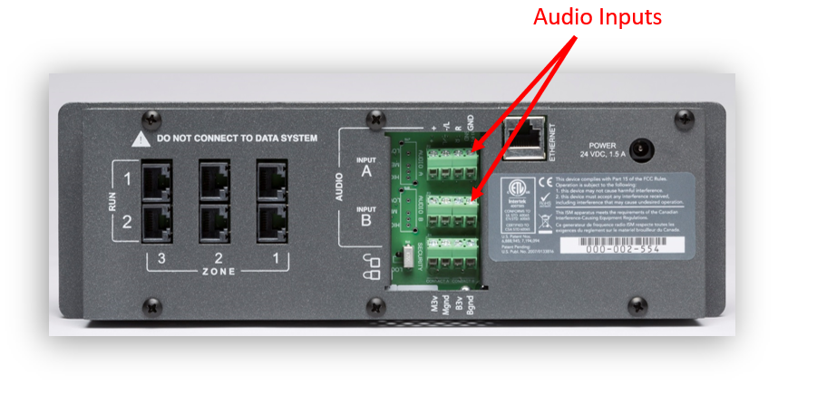
Connecting an Input
Be sure to power off the control module by unplugging the power cord from the wall outlet. Use the diagrams below to connect the cables from your audio input to the back of the control module. For the Qt 100, you will need to remove the plastic backing. For the Qt 300/600, you will need to flip the control module down in the housing to access the inputs. Inputs A and B are clearly labeled on the PCB of the Qt 300/600.
Balanced Audio Inputs
Connect the corresponding signal wires to the “+” and “-” ports on the control module’s input.

Unbalanced Audio Inputs
Mono Signals
Connect the signal wire to both the “L” and “R” ports on the module’s input.

Stereo Signals
Connect the corresponding signal wires to the “L” and “R.” Connect the ground wire to “GND.”

Adjusting Input Volume
Each Qt control module is pre-configured to mute any auxiliary input upon shipment. The volume level of each input is controlled per zone through the front panel of the control module or using the MCS software web GUI of the Qt 300/600. Navigate through the front panel LCD to the desired Zone and Input, and adjust the volume using the 'Up/+' and 'Down/-' levels.
Troubleshooting
If the volume is turned up on each zone and if the volume is still too low, you will need to isolate the problem to the cable or auxiliary device. First, check to ensure the volume on the audio source (ie. volume on an iPod) is turned to its midpoint. Then, check to ensure the cable was prepared correctly. The correct method for creating a cable is as follows:
- Take a 1/8” stereo cable or RCA cable that connects to the music source and strip back the main insulation 1/2” to expose the bare wire, including the red and white insulated wires.
- Separate the insulated conductors from the exposed outer strands. This is the ground
- The insulated conductors are the left and right signals and will correspond to the “L” and “R” ports on the control module. The exposed outer conductor will connected to the "GND".