Qt-RC Room Control overview
 The Qt Room Control is used to adjust sound masking levels in small spaces where local adjustment is necessary such as healthcare exam rooms and patient rooms (see Note below). These controllers are installed into single gang decora plates and are powered via Category cable from the control module. They have a six-way knob that decreases the level by 10 dB / 12.5 dB at the lowest position. There is also a DIP-switch on the circuit board that configures the lowest position as a mute.
There are two Qt-RC options available depending on which system is installed, the Qt-RC2 and Qt-RC3. The Qt-RC2 supports control of up to eight adjustable emitters whereas the Qt-RC3 supports control of up to eight adjustable emitters or 14 active emitters on the room port. Due to this, Qt-RC2's are required for all Qt100 systems (and Qt X systems with Adjustable Emitters) and Qt-RC3's are recommended for Qt300/Qt600 systems (and Qt X systems with Powered Emitters).
Note: It is not a recommended practice to use Qt Room Controls for private / open office settings as user control is strongly discouraged. Sound masking affects the talkers signal as experienced by the listener's location (not the space where the talker is speaking). Therefore user adjustment of the sound masking signal downward will permit conversations to be clearly overhead reducing privacy levels.
This article will serve as a guide to installing and using Qt-RC.
Wiring
These units can be installed in the middle of an existing run or added as a separate run from the control module. On the back of the Qt-RC there are three RJ-45 ports labeled IN, Room and Out.
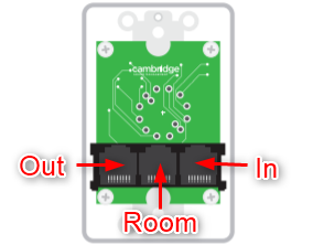
In - This connection should be made from the control module or a branch off of an existing emitter run.
Room - Emitters connected off of this run will be controlled by the knob. Only 8 adjustable emitter can be connect or 14 active emitters (Qt-RC3 only).
Out - This continues the existing emitter run unaffected by the controller to feed more emitters or more Qt-RC's.
Switch - A small switch on the circuit card may be toggled to make the last step position "Mute" or "Maximum Attenuation" dependent on desired outcome.
The signal attenuation steps are as follows;
RC-2 Minus 2.5 dB increments / Five attenuation steps total / Maximum attenuation = -12.5 dB (or switch selected "Mute" for final step)
RC-3 Minus 2 dB increments / Five attenuation steps total / Maximum attenuation = -10 dB (or switch selected "Mute" for final step)
When a Qt-RC is installed on a run the total number of emitters allowed is affected. For each controller on a run, the maximum should be reduced by one or two emitters dependent on model of room control in use. For instance, a Qt100 run can support 60 adjustable emitters, but with five Qt-RC2's only 55 emitters can be powered as each RC-2 will count as one emitter. This count doubles when the RC-3 is deployed on a Qt300/600 system as each room controller decreases the power available to the cable run by two emitters. Take care to include any emitters connected to the Room outputs when calculating total emitters permitted on a cable run.
The following applies to the reduction of emitters based on the room control in use;
RC-2 - Each RC-2 will reduce the number of emitters powered on the cable run by a count of one emitter.
RC-3 - Each RC-3 will reduce the number of emitters powered on the cable run by a count of two emitters.
Maximum room control count per cable run of a control processor - No more than eight room controls should be present on a single cable run of a control processor. Regardless of model chosen (RC-2 -or- RC-3) the maximum number of room controls must remain fewer than eight per control processor cable run. Too many room controls can result in a error code on the controller itself indicated as a zone fault.
Design
One Room
If only one controlled room is needed, then installation could look like this:
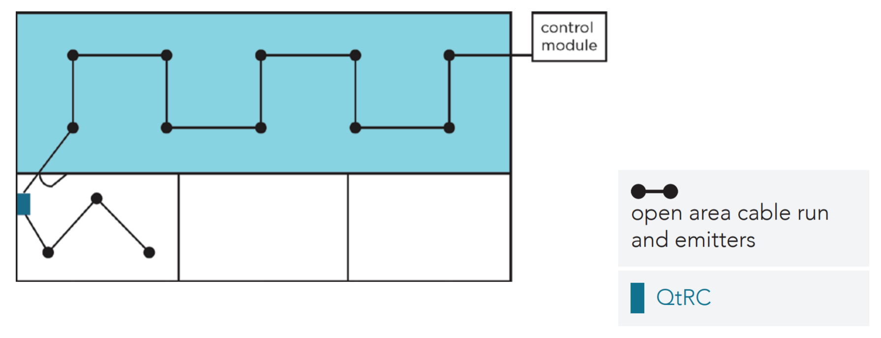
The Qt-RC is installed at the end of the run of emitters so that minimal cabling is required. This design is best for small systems where one or two rooms are needed.
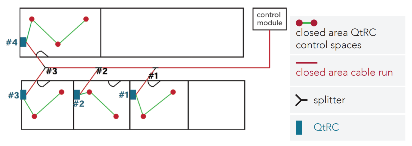
One Zone
When many rooms need independent control all Qt-RC's can be run off of one single zone. This design utilizes splitters to allow for more central wiring and then breakouts to different rooms.
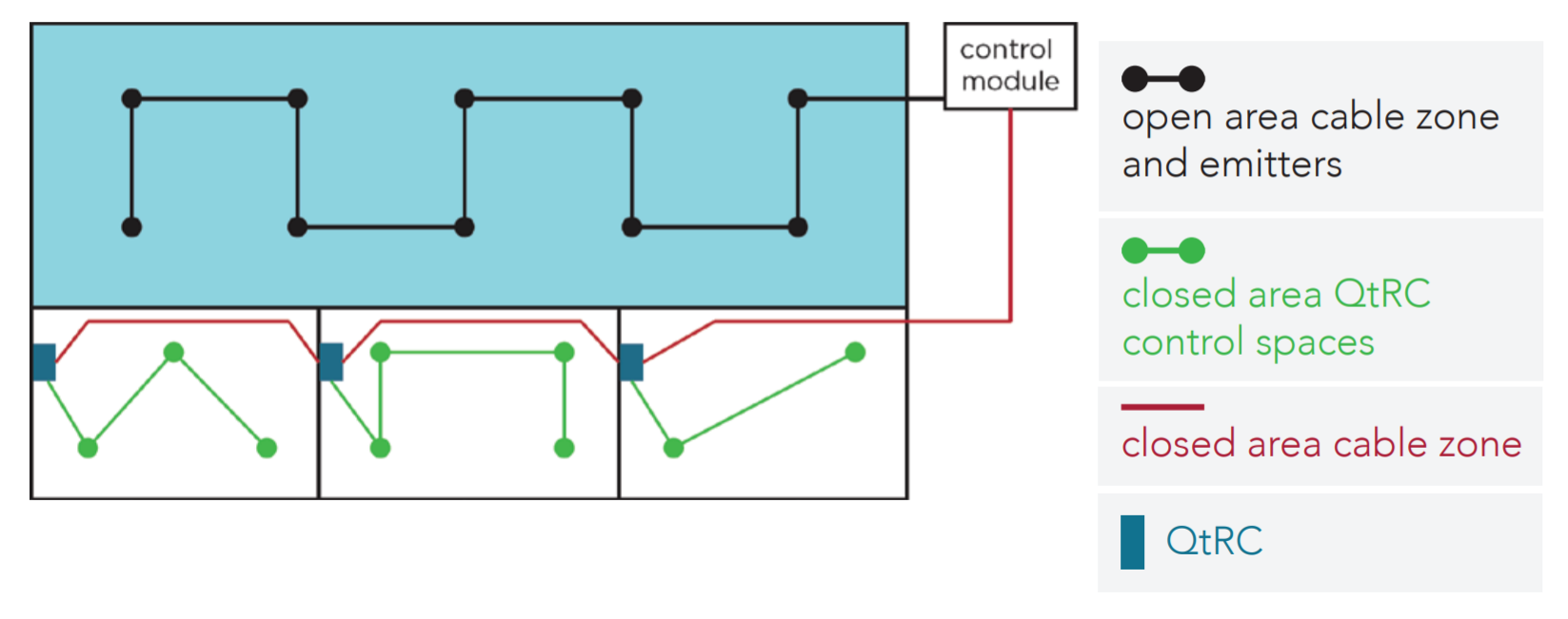
Two Zones
In larger systems a hybrid approach is commonly used. Here there is a normal masking run using one zone and a second zone to facilitate all of the Qt-RC's.