Five-zone Qt X Office Sound Masking, Paging, and BGM
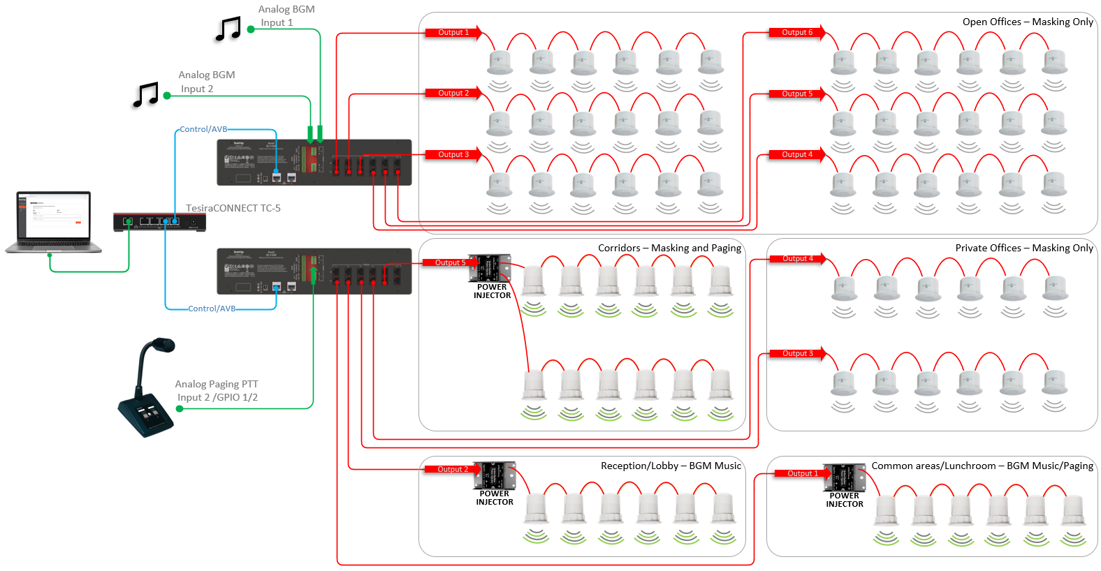
This design example features Qt X platform hardware providing centralized control of masking, music, and paging in a small to mid-sized single-level office space. The design contains a central equipment location with a paging microphone location at a reception-area desk. Background music playback is provided with multiple channel selections available to the required zones. The zones include a combination of active and passive emitters to support sources and masking as required in the design. The emitter types are shown in the equipment list as an example, however, the design quantities should vary by building size.
The intent of this example design is to show the required component types for this application.
System functionality scope
Sound masking, music, and paging:
- 5 Sound Masking Zones to accommodate
- Open office spaces
- Private offices
- Corridors
- Reception
- Common areas and lunchroom
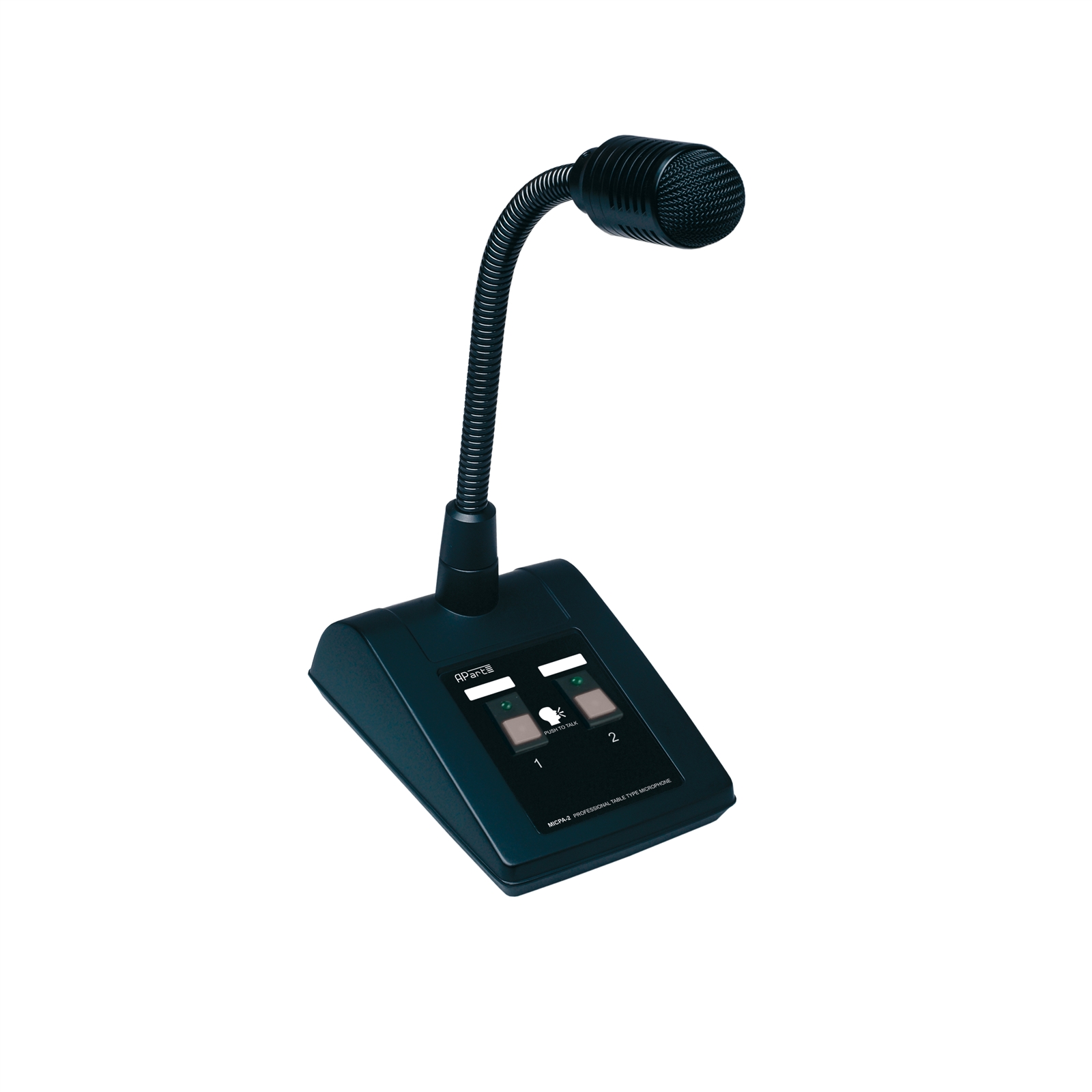
- 1 Paging Station to provide live paging from the reception area
- 2 Paging selections capable of receiving the same, or unique pages. Zones served by each paging selection will be defined in the Qt X configuration file.
- 2 Background music sources
Equipment list
Biamp equipment used in this project: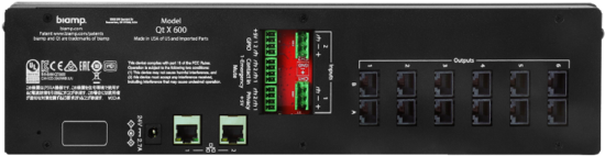
-
(2) Qt X 600 Masking Generators
-
(1) MICPAT-2 Tabletop Paging Microphone
-
(2) Owner-furnished background music players
-
(1) TC-5 AVB device
-
Qt® Emitters (quantity varies by sq footage)
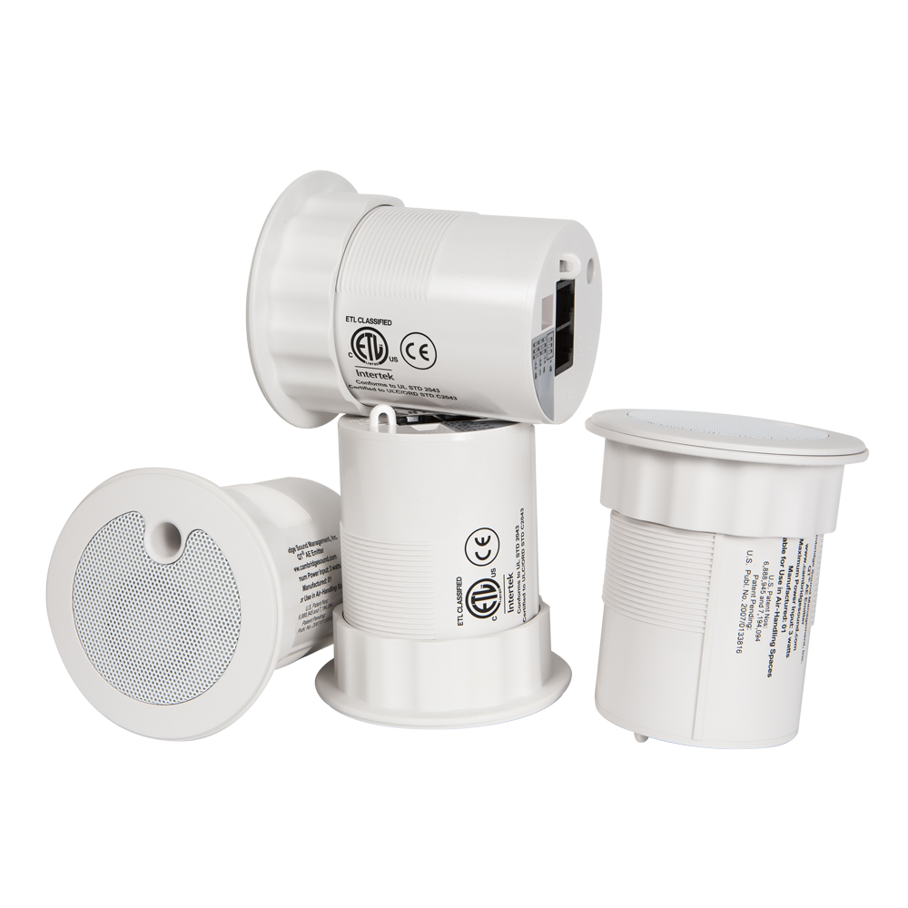
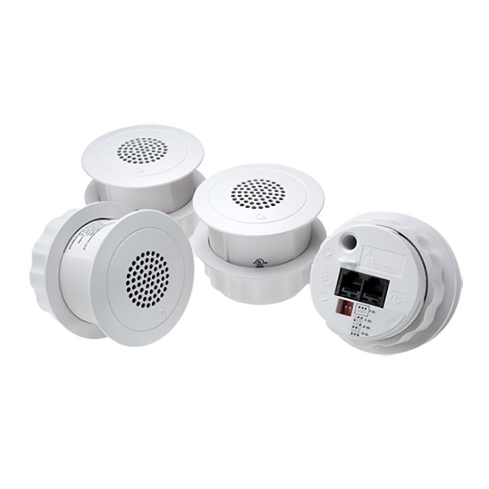
-
Qt® Active Emitters (quantity varies by sq footage)
-
(3) Qt® PI-AE Active Emitter Power Injector
-
(1) Qt® PS-AE-3 Active Emitter Power Supply
Example files
The example file for this system design template includes the Qt X configuration file programmed to fit the design criteria for this design. For other designs, it may be changed as needed or simply used as a reference.
The Qt X software application is required to open this configuration file and may be downloaded here (Select Cambridge under the "Products" dropdown).
Design file download
This downloadable file contains the Qt X .qdd configuration file for the example application in this article.
Networking details
The Qt X controllers specified in this design use AVB media to transmit source audio between devices. A TC-5 from Biamp has been added to the equipment list to support this design need. Dante versions of the same hardware could also be substituted and used with an unmanaged switch to support this design. If using AVB, verify that the switch used supports AVB and has a running license.
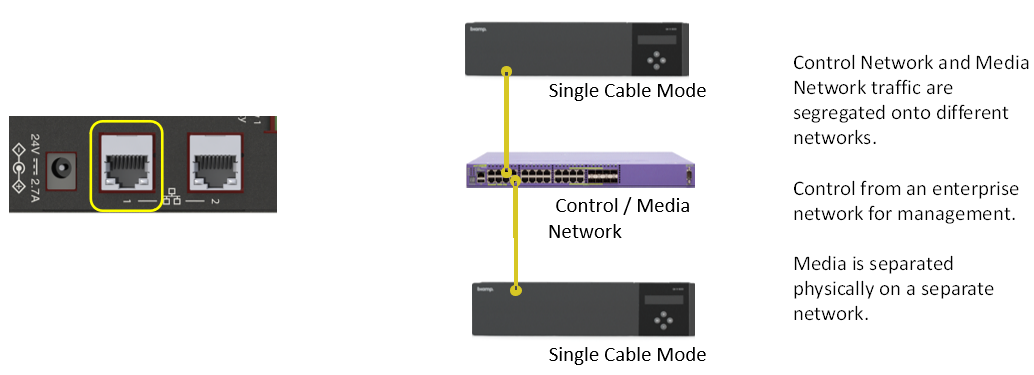
By default, all Qt X controllers are in Single Cable network mode with DCHP enabled.
The host PC needs to be on the same subnet or set to link local to discover the Qt X controllers. Verify the PC's network settings are in the same range as the IP for Control/Media on the front panel of the controllers.
System setup
This design file is configured for the Qt X controllers in the equipment list of this article. However, you do not need the physical hardware present to view the design file or make edits to it. The file can be used as a point of reference to understand the controller and zone programming as it applies to this design.
To load this configuration to hardware, the available hardware needs to be the same model number as shown in the design. Additionally, the factory configuration must be cleared before blocks can be assigned to physical devices. The devices must all be set to the same media type.
Devices
The Qt X controllers may be removed and replaced as needed to match available hardware to test functionality. The design software elements allow for adding or removing controllers from the toolbar to floor plan design. The (2) Qt X 600 controllers required for this design have been added.

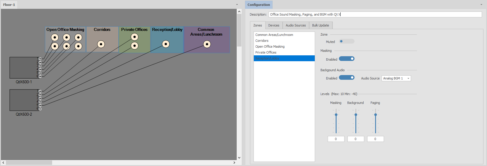
Zones
The design will have all the required zones and emitters added to properly meet the scope requirements. Zones have been named in the properties window to match the design drawing. Default zone colors have been changed to help with visualization on the floor plan.
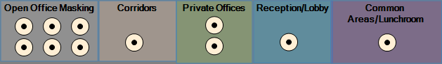
Note: It is important to note that the emitter icons are representative of a run of emitters, or a single emitter speaker. It is not required to draw all speakers in the floor plan view.
Emitter type
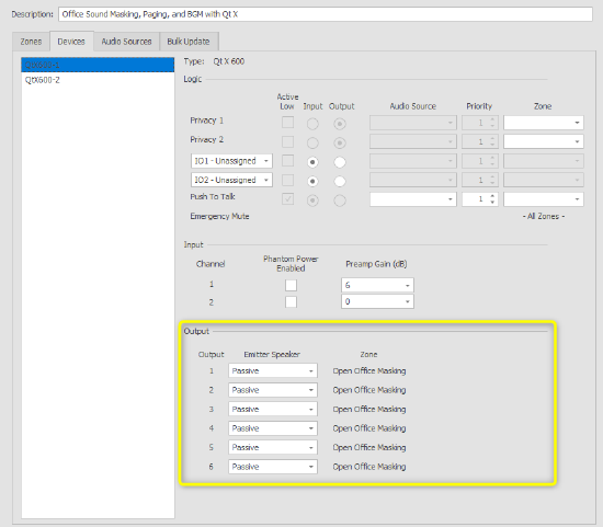
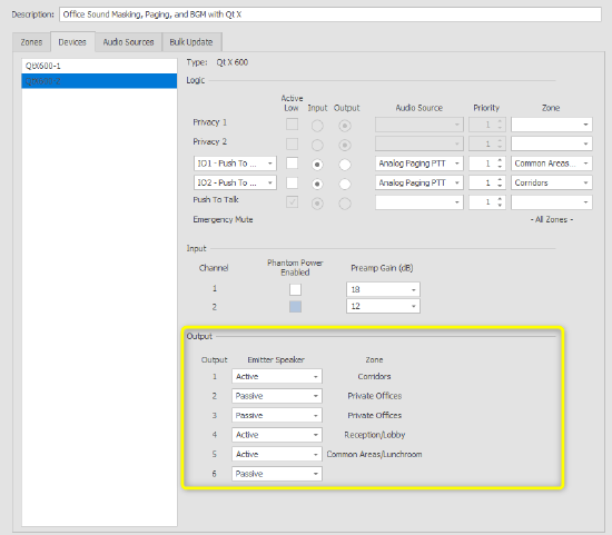
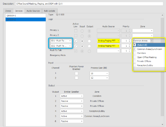
All emitters in the configuration file are set to match the zone sources. Open office masking and private offices are assigned as passive, while other areas that require paging and background sources are set to active to match emitter requirements. This setting is located in the devices tab under output.
Emitters connected to devices QtX600-1 & QtX600-2
Audio Sources
Analog audio sources have been added and assigned to devices to support the BGM and paging requirements. From the "Intents" dropdown, you may assign the source to be available as a Background, Paging, or both. This selection influences source visibility in zone and logic tabs. Once added, BGM sources can be assigned to required sones via the "Zones" tab dropdown menu. Before sending the configuration, enable background audio on all required zones. These background sources can be selected and changed in the running configuration once loaded to hardware.
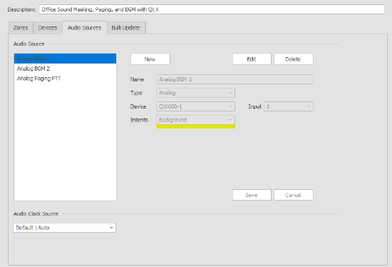
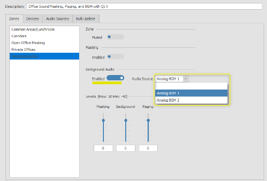
Note: Source assignment in the Intents dropdown will influence where the source is visible in the assignment tabs. Only sources selected as background will be seen in the background audio dropdown under the Zones tab. Using logic to trigger paging sources to the required zones rather than assigning them to a zone at all times is recommended. This allows for paging to be active only while required and to duck the background music. Paging input sources are programmed in the logic section.
Logic
GPIO inputs 1 and 2 are programmed to trigger Push to Talk pages to the selected zones in this example. Both inputs have been selected as “active low” to allow for paging to be active when a contact closure is sensed. Logic is programmed in QtX600-2 to follow the signal flow wiring location. Each GPIO has the same audio source but allows paging to each area discreetly or at the same time based on selection at the paging station. The selection of required zones is handled in the dropdown menus.
Source input gain and phantom
Source input gain and phantom power assignment may be set during configuration or after a file is sent to the hardware. All analog inputs default to 18dB and can be increased or decreased in 6dB increments. Live metering is available on running configurations to allow for proper gain staging of inputs to ensure the best signal-to-noise ratio.
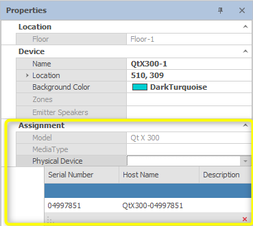
Device assignment
All Qt X controllers ship with a running default configuration file. When a design created in Qt X software devices are added and not yet associated with actual hardware that will be installed. This allows for a configuration to be done with no hardware present. For a configuration to be loaded to hardware, the default configuration must be cleared so that devices may be assigned to blocks in the software from the properties window.
To clear a configuration, select the system from under the Devices and System tab, then clear.
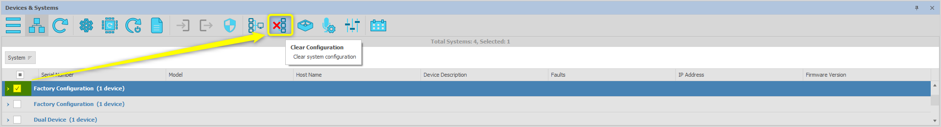
Once the device(s) have been cleared, they will be available to assign to the devices in the configuration file via the Properties window.