Small House of Worship
This system design template shows how Tesira products can be used in a small House of Worship installation. This example focuses on a system that is designed to run and be easily controlled without having a dedicated operator or mixing board.
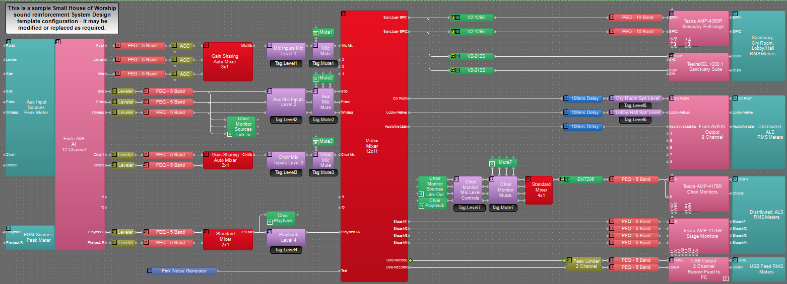
The primary system will consist of inputs from Pulpit, Lectern and Altar locations for speech reproduction throughout the sanctuary and distributed feeds. In addition, there will be inputs for choir, piano, and soloist microphones that will feed the sanctuary and supplemental powered choir monitor. Playback audio and USB recording is also supported in this system. Simple system level and mute control of the sanctuary system will be provided with a TEC-1 wall controller in the main worship space. There will also be two additional TEC-1 controllers to allow for zone control in the Cry room and Lobby/Hallway areas. A Biamp Canvas file is provided for more advanced mixing and control capabilities.
Room design
Small House of Worship Functionality Scope:
- Auto-mixed Pulpit, Lectern, and Altar microphone inputs with master level adjustment.
- Auto-mixed Choir microphone inputs with master level adjustment.
- Wireless, Piano, and Solo microphone inputs with individual level adjustment per channel.
- Full-Range 2-way point source speakers
- Dual sub-woofers to support system audio
- Column mounted choir monitors
- Stage monitor feeds
- 70V distributed ceiling speaker feed for cry room area.
- 70V distributed ceiling speaker feed for Lobby and Hallway areas.
- Assistive Listening system feed.
- Two-channel USB record feed to PC.
- Source level mixing controls via wall mounted TEC-1 wall panel in Sanctuary.
- Zone level control via wall mounted TEC-1 wall panel in Cry room.
- Zone level control via wall mounted TEC-1 wall panel in Lobby area.
- User interface for additional control via Canvas software.
Equipment list
Below is the list of Biamp equipment used in this project:
- 1 - TesiraFORTÉ AVB AI 12 mic/line level inputs; 8 mic/line level outputs with integrated USB audio
- 1 - TesiraCONNECT TC-5 5 port AVB room expander with 120W of PoE+ budget.
- 3 - Tesira TEC-1 Tesira PoE Ethernet control device: in-wall/surface mount
- 3 - PH POE36U-1AT-R Gigabit PoE+ Injector, IEEE802.3af compliant, IEEE802.3at, PoE capable network switch, or equivalent PoE injector
- 1 - Tesira AMP-4350R Four channels; 350W per channel, Dual AVB ports
- 1 - TesiraXEL 1200.1 Four channels, 1200W total output, Daisy chain AVB ports
- 2 - Tesira AMP-4175R Four channels; 175W per channel, Dual AVB ports
- 3 - Tesira TEC-1 Tesira PoE Ethernet control device: in-wall/surface mount
- 1 - AMP-460H 4-Channel, 60W class D amplifier; supports both 70V and 100V constant-voltage speaker systems
- 2 - Community V2-1296 12-inch Full-Range Two-Way Medium Power Point Source (90° X 60°) ; 200W continuous @ 8 ohms
- 2 - Community V2-212S Dual 12-inch Versatile Cost Effective Subwoofer, Nominal Beamwidth (H x V): 360° x 180°; 300W continuous @ 4 ohms
- 2 - Community ENT206 Two-Way Compact Column Point Source Loudspeaker, Nominal Beamwidth (H x V): 140° x 20°; 150W continuous @ 8 ohms
- 4 - Community MX8 8-inch Compact Coaxial Two-Way Monitor, Nominal Beamwidth (H x V): 115° x 115° (conical); 150W continuous @ 8 ohms
- Apart CM60DTD 6.5" two-way, thin edge ceiling loudspeaker, with back can. 70V transformer power taps in watts 60-30-15-7.5-3.75. (Quantities as needed to meet project scope)
Note that other non-Biamp equipment is required, including the microphones, stereo program source device, network switch, and control PC.
Example file
The example file for this system design template is set up with all the analog audio I/O, processing, and control points required for the functionality scope, and is ready to load to the system. In the file, the matrix routing is setup for sources to feed to all locations as a base starting point. These routes may be changed or modified as needed to fit specific the design application.
The file's Equipment Table is populated with proper hardware to match the layout, but will need to have serial numbers and proxy host assignments added before loading the file to system. The file download includes an optional Canvas control file that can be used for advanced routing and control of the system if required. The sanctuary TEC-1 controller has a multi-page configuration with a home navigation page and sub pages for zone level adjustment. Secondary TEC-1 controllers are used for individual zone level adjustment only.
To assist with deployment and commissioning of systems which include Community speakers, a Tesira Library File (.tlf) has been created. This includes custom blocks with Biamp's recommended EQ curves to optimize the sound the included loudspeakers in this design. The custom blocks have been included in this system design template file. These blocks can also be found in the Processing Library in Tesira software.
The .zip file below contains the example Tesira and Canvas configuration files for this Small House of Worship application.
File Download: Small House of Worship sound reinforcement system.zip
Networking details
The small House of Worship application will make use of the control and AVB network interfaces of the hardware to achieve a fully functioning room environment. To get this design properly running on our hardware, we will need to prepare the control and AVB sides of the network. This system is small enough to be placed on a very small local AV switch with direct AVB connections between devices, but is also equally capable to be integrated into a larger network sharing switches for the control and AVB traffic. For a more detailed guide on how to implement in a larger range of network applications, it would be helpful to reference our Tesira Network Infrastructure article.
Tesira and TEC-1 devices will need to be discovered in Tesira software before the configuration can be sent. The PC must have a unique IP address in the same subnet as the TesiraFORTÉ. Both devices are configured from the factory with DHCP or Zero Conf (Link Local) address. If you wish to verify your PC network interface is set correctly, please review the Setting an IP address section. More details of system connections can be found here.
In this application, the TesiraFORTÉ AVB AI and AVB amplifiers will be connected with the TesiraCONNECT TC-5 using a separated networks topology.
Setup Requirements:
- Control network switch with sufficient ports and/or PoE capable port(s)
- TesiraCONNECT TC-5 device provides 5 ports of AVB and 120W of PoE+ budget. This will serve to connect all AVB devices
- 802.3af (Class 1) PoE injector for powering each TEC-1 controller or PoE capable port. Each TEC-1 requires 3.2W of power
- Follow proper setup steps for discovery and assignment of TEC-1 controllers as shown in system control section of this article
- Connection to Owner PC and network for Canvas user interface control
After these control and AVB network setup steps are complete, you will now be ready to send your compiled system configuration to the hardware.
Note: As this system does not make use of a remote or rack-mount expander, the AVB will communicate over Layer 2 networking and not require IP addresses on the AVB side of the network.
Audio setup
- Follow Gain Structure best practices to set input and output levels of microphones and sources. Input and output gain levels have been left at default settings for integration flexibility of the file. Input and Output metering has been added to assist with setting gain structure within the file. Additional meters can be added to the file as required to allow for additional detail at point along the signal path.
- The Tesira amplifier in the example file uses a constant voltage output per channel at 70V. Properly tap Sanctuary and Distributed speakers to match with provided amplifier power. This amplifier may be substituted to fit the design application or speaker type as needed.
- Connect USB to PC for soft codec integration if desired. The file is setup to provide 2 channels of audio to the USB interface. This may be changed to provide up to 8 channels of audio output if desired. Reference the USB interface setup document if needed.
- Gain sharing auto mixers may be changed as needed to fit the specific design application. In the example file there are two gain sharing auto mixers in place for the main platform and choir microphones.
- Level and mute controls have been added to the file pre and post matrix mixer. These are added for flexibility to meet the design criteria and tastes of the client or integrator. These level controls have been set with recommended maximum and minimum values in place, but can be adjusted to fit the needs of the space.
- Mute logic has been added to the Sanctuary TEC-1 controller so that the triangle indicator in the TEC-1 indicates the mute state of the selected channel. This will allow for sources to be toggled to mute. The triangle indicates that the corresponding channel is muted. This may be changed or modified to fit the end user control needs.
- The TEC-1 hardware has been setup with controls for level and mute functions. In the main sanctuary, the wall controller has mixing controls for both main sanctuary and choir monitor speaker. There are TEC-1 controllers for the cry room and lobby/hallway areas that allow for overall zone level adjustment in each area.
- Uber Filters have been added to all input signal paths to allow for any additional equalization as needed to sources. Additional filtering or dynamics blocks may be added or changed as needed to achieve the desired results in the file.
- Graphic equalizer blocks have been added to the file output paths to allow for room tuning and optimization. These may be changed as needed to fit the design application.
- Choir monitor sources have the ability to be sub-mixed separately from the main sanctuary sources. This functionality may be modified as needed to fit the design.
- Changes to matrix mixer can be made as needed to allow for appropriate sources to feed sanctuary, choir and distributed zones to fit the design application.
System control
TEC-1 Setup: The TEC-1 wall mounted controllers in this system are a standard Ethernet device and require 802.3af Class 1 PoE. The default network configuration of TEC-1 units is DHCP, so if there is no DHCP server on the Tesira network the units will revert to link local addressing schemes (169.254.xxx.xxx, netmask 255.255.0.0). The TEC-1 will display "Waiting for Configuration..." on the screen until a configuration file has been loaded to the Server associating it by its Device ID. Each TEC-1 unit requires an unique IP address. The Device ID of the TEC-1 is used to associate the block with the physical TEC-1, it needs to be set in 2 places: the TEC-1 processing block and in the TEC-1 hardware. The units in the file are setup with their device ID set and will need to have the hardware set to match. Each ID in shown a text box next to its associated TEC-1 block in the file. The Sanctuary TEC-1 Controller has been setup with a multi page configuration with the main selections on a home screen and choir monitor specific controls on a sub page. Additional info on multi page setup can be found here and includes guides for the RED-1 controller that can also be applied to the TEC-1 programming.
Biamp Canvas Sofware: An optional Biamp Canvas configuration layout has been provided for this application to be used as an additional point of control for the system integrator or operator. This is an optional part of the system, and is not required for the operation of the file. This Biamp Canvas layout is setup with basic controls for the system to allow for level adjustment, source selection, routing, and muting. It is created as a starting point and may be modified as needed to fit exact needs of the design application. The Canvas help file can be found here for reference.
Control System Integration: The example Tesira configuration file for this system design template has been setup to allow third-party control systems to easily control the Tesira system if desired. There are control points for Level and Mute, already in place to allow for you to use as it as-is, or add to as needed to suit the needs of the design. Control points within the file have been left at the default instance ID tag. These tags can be changed as needed to suit the programmer workflow or standardization.