Avaya CS1000 configuration for Tesira using SageVue
Biamp’s VoIP-enabled products have the ability to make and receive phone calls over many different Voice-over-IP (VoIP) systems that adheres to the SIP (Session Initiation Protocol) standard. This article details the steps required to configure an Avaya Communication Server (CS1000) VoIP system to work with Biamp's Tesira VoIP products and configuring those products using using SageVue.
Please first review the requirements for using the VoIP web interface to configure a Tesira VoIP endpoint.
Avaya creates and maintains application notes for certified products manufactured by Avaya's DevConnect Technology Partners. Avaya's full application note for configuring an Avaya SES system to use Tesira VoIP endpoints can be downloaded from this link. Information specific to creating the endpoint is below.
Avaya Configuration
Configure Avaya CS 1000
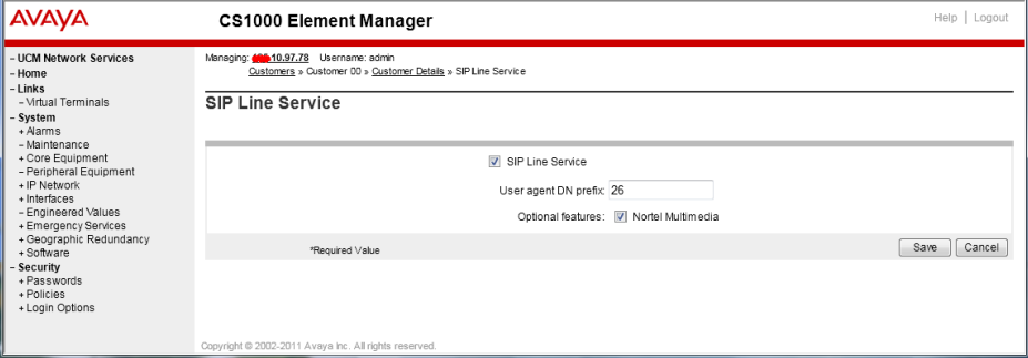 |
|
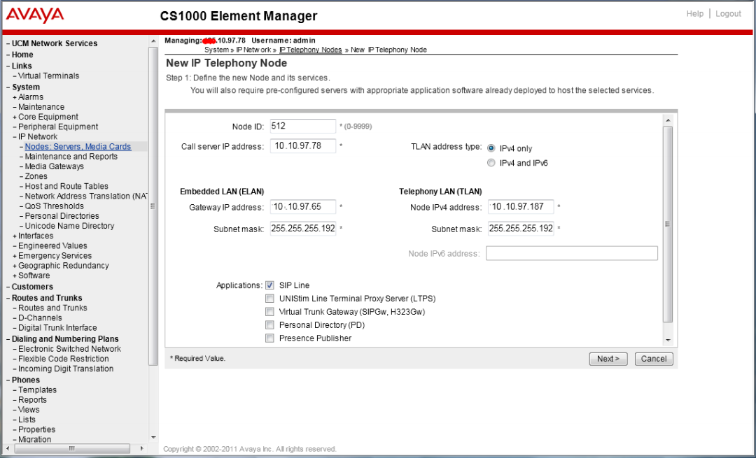
2. Create SIP Line Telephony NodeOn the EM page, navigate to menu System, IP Network, Nodes: Servers, Media Cards. Click Add to add a new SIP Line Node to the IP Telephony Nodes. The new IP Telephony Node page appears as shown to the right Enter the information as shown below:
Once that is completed click "Next" |
|
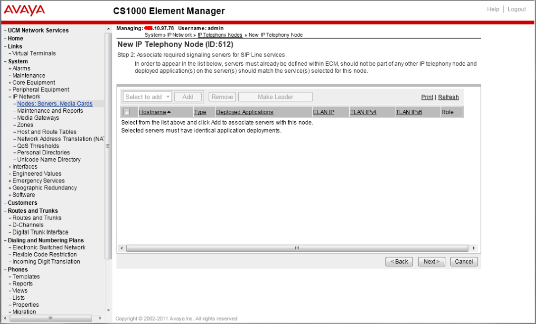
3. Adding a Server to the NodeNew IP Telephony Node with Node ID, will appear as shown:
Once that is complete click "Next" |
 |
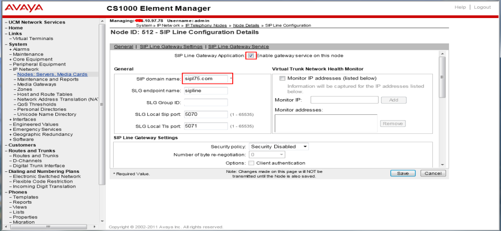
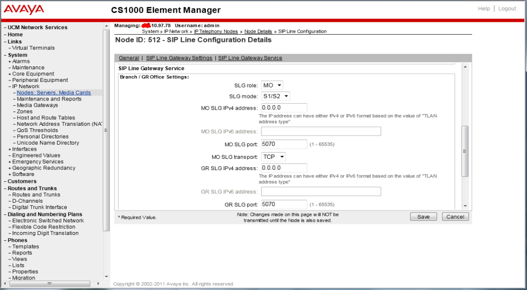
4. Configuring SIP Domain/Gateway
Scroll down to the Branch / GR Office Settings section under SIP Line Gateway Service:
Once that is Complete Click "Next" and then click "Transfer Now"
Select the SIP Line server associated with changes and then click on the Start Sync button to transfer the configuration files to the selected servers.
Note: The first time a new Telephony Node is added and transferred to the call server, the SIP Line services need to be restarted. To restart the SIP Line services, log in as administrator to the command line interface of the SIP Line server and issue command: "appstart restart." |
|
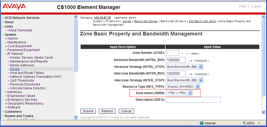
5. Creating a Virtual Trunk ZoneOn the Element Manager (EM) page, navigate to menu System, IP Network, then Zones. The Zones page appears on the right. On this page select Bandwidth Zones link. On the Bandwidth Zones page click on the Add button, the Zone Basic Property and Bandwidth Management page appears as shown. Enter a zone number in the Zone Number (Zone) field. In the Zone Intent (ZBRN) drop-down menu select VTRK (VTRK).Leave other fields at default values and click on the Save button to complete adding the Zone.
Note: Repeat the step above to create another zone for the SIP Line phone; however remember to select MO (MO), instead of VTRK in the field Zone Intent. |
 |
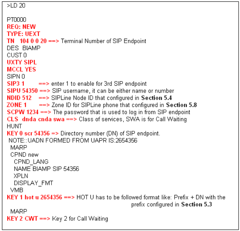
6. Create SIP Line PhonesTo create a SIP Line phone on the Call Server, log in as administrator and use overlay command LD 20 as shown to the right.
The bold fields must be properly inputted as they are configured on the Call server, for other fields press to leave it at default values. NDID 512 ==> SSIP Line Node ID configured in Step 2 ZONE ==> Zone ID for SIP Line was configured in Step 5 HOT U ==> The prefix was configured in Step 1 |
|
Once you have entered this information move on to configure the Tesira VoIP endpoint
Tesira Configuration
Accessing VoIP settings in SageVue
|
|
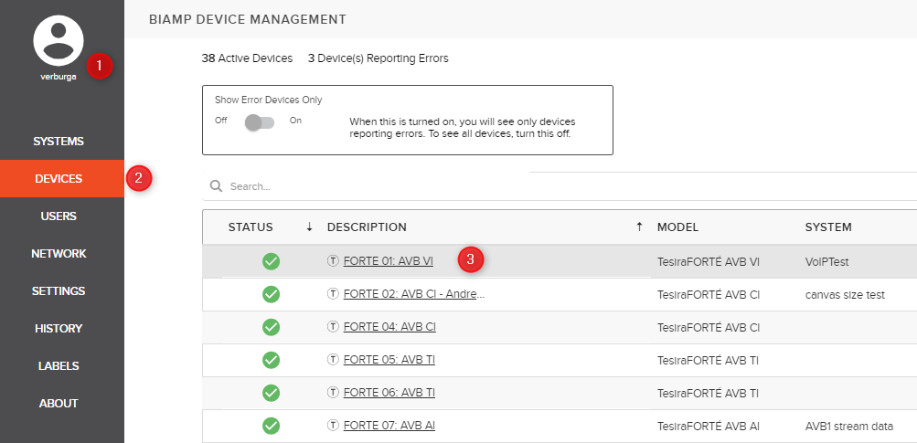

- Open a browser and login to your Sagevue webpage.
- Navigate to "Devices" on the right side of your browser.
- Click on the device description of a device running a configuration that has a VoIP interface
- Navigate to the VoIP configuration tab. (If you cannot access the VoIP settings make sure your account has read/write permissions for VoIP settings. More information on user roles can be found on the online SageVue help page.)
- Select the correct interface that adjustments are going to be made on.
- If you'd like to set the same settings on all VoIP interfaces within this device, enable the "Configure all VoIP cards in this device" option. Note that only fields highlighted in yellow can be updated on multiple endpoints at once.
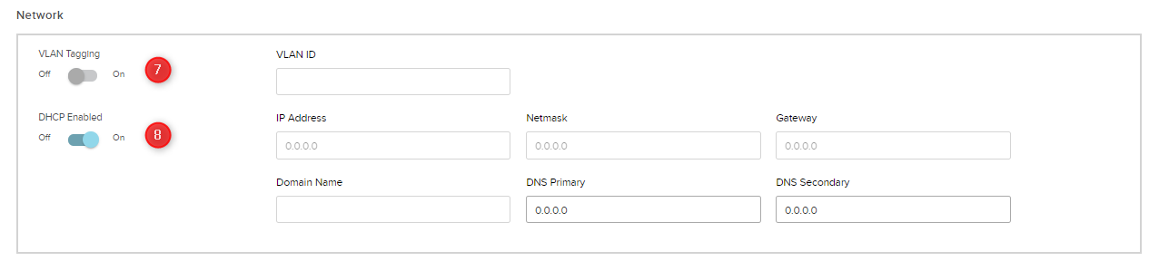
Network Configuration
- Under the Network region of the screen, set “VLAN Tagging” to “Enabled” if your VoIP network uses a tagged VLAN. If the network uses an untagged VLAN or no VLAN, leave this value as “Disabled”. If VLAN is enabled, enter the correct VLAN ID.
- Leave “DHCP” set to “Enabled” if the Tesira endpoint will obtain an IP address automatically from a DHCP server. Otherwise, set “DHCP” to “Disabled”, and manually enter an appropriate static IP Address, Subnet Mask, and Gateway for the Tesira.
Protocol Configuration
- Select the line you are updating.
- Set Proxy Vendor to Avaya CS 1000.
- In the Extension field fill in the SIPU field. (see "Configure Avaya CS 1000", step 6)
- In the Display Name field, optionally enter a name for the extension for Caller ID purposes. Note that this name may be overridden by the proxy server, and therefore may not show up as the Caller ID name.
- In the Authentication User Name (Extension) fill in the SIPU field (see "Configure Avaya CS 1000", step 6)
- In the Password field fill in the SCPW field.(see "Configure Avaya CS 1000", step 6)
- In the SIP Proxy Address Enter the IP address of CS 1000 SIP line server. (see "Configure Avaya Cs 1000", step 2)
- In the SIP Proxy Port Field Verify that the port is 5060, 5061, or change it as needed. (see "Configure Avaya CS 1000", step 4)
- If you’re configuring two lines, select “Line 2” from the drop down and repeat steps 10-16.
- All other settings can remain at their default values in most cases.
- Once all settings have been added, click the Update button and the settings will be written to the Tesira VoIP interface.
- More Advanced features such as transport type, QoS settings, and Local Dial Plan can only be changed via the Tesira software or the VoIP webpage. These settings are optional and often don't need to be changed from their default values.