Analog telephone interface basics
Communication plays such a major role in our day-to-day lives that it is no surprise for the telecommunication industry to grow at a rapid pace. As a leader in the DSP and audio conferencing market, Biamp Systems first introduced the TI-2 card, a dual analog telephone interface, and followed with the Nexia TC interface, then VoIP technologies.
This article will go in depth on the basic knowledge required to install, program and troubleshoot our analog telephone interfaces. Starting from the basics of telephony, we will then move on to more advanced programming techniques.
Analog telephone interfaces
Telephone Interface card:
TI-2 (Audia)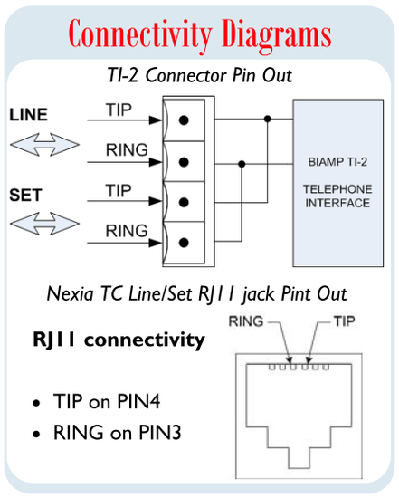
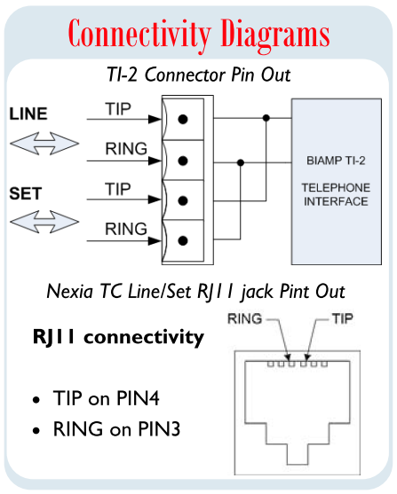
The TI-2 card is a full-featured dual channel analog telephone interface card including Line Echo cancellation, Caller ID, Ring detection/Validation, Auto-answer, Auto-disconnect, DTMF and Call progress decoding just to name a few. The connectivity is on a removable terminal block connector with “spring cage” contacts. A SET connector allows for a telephone handset to be connected in parallel with the telephone line interface. (See connectivity diagram)
Nexia TC telephone interface
The Nexia TC has a single channel interface with similar features as the TI-2 but with RJ-11 connectivity. Only the 2 center pins of the connector are being used. A SET pass-through connection is also available. (See connectivity diagram)
STC-2 (Tesira)
The Tesira STC-2 is a modular telephone interface card for use with Tesira SERVER and SERVER-IO devices. The STC-2 allows a Tesira system to connect directly to up to two standard analog telephone lines. Being more than just a normal "hybrid," each channel includes line-echo cancelation, noise suppression, caller ID decoding, ring detection/validation, DTMF decoding, and call progress tone decoding.
The device is supported via software using the Telephone Interface Component Object. Each STC Input is also able the be associated with the DTMF Decode and Dialer blocks.
Up to six (6) STC-2 cards are supported in a Server I/O chassis.
TesiraFORTÉ TI telephone interface
The TesiraFORTÉ TI has a single channel interface with similar features as the STC-2. It uses an RJ-11 for connectivity. Only the 2 center pins of the connector are being used. A SET connection is not available.
Vocia POTS-1 Connection
A LINE and SET RJ-11 connection is provided per telephone line. These are wired in parallel and allow a local handset to be used on the SET line.
|
Pin |
1 | 2 | 3 | 4 | 5 | 6 |
|
Function |
NC | Loop | Ring | Tip | Loop | NC |
Telephony Basics
Having all sorts of acronyms, the telephone system terminology can become confusing if you don’t understand the following:
- Plain Old Telephone Service (POTS) refers to the standard low speed and limited bandwidth (180 to 3200Hz) analog service used to deliver telephone services to homes and businesses. Current modulation on a twisted pair of wires is used to communicate the audio information in full duplex. The STC-2, TI-2 and Nexia TC can interface with POTS lines.
- Public Switched Telephone Network (PSTN) refers to the worldwide public telephone network. Initially composed of analog trunks, the PSTN is now almost entirely digital and includes cell phones. It is the main backbone interfacing with POTS.
- Private Branch Automatic eXchange (PBX/PABX), also known as a phone switch, is mainly used to route and interface multiple internal phone extensions to the PSTN. PBX are very common nowadays and present in most corporate offices. You will most likely interface with a PBX whenever installing a Tesira / AudiaFlex / Nexia TC DSP platform in an office complex with an analog phone line.
Voltage and Current
Voltage and Current monitoring are useful troubleshooting tools to test your analog telephone line, they are found in the Control Status block.
In North America, TIP conductor is typically red and the RING conductor usually green. If colors are different than the norm, use a voltmeter to identify wires. Expect a negative DC voltage between the TIP and RING (usually between -54V to -40V).
| On Hook | Off Hook | |
|---|---|---|
| Voltage | -54V to -40V | -20V to -5V |
| Current | 0mA | 23mA to 35mA |
The typical voltage on POTS/PBX lines varies but one should expect between -54V to -40V when ON Hook (no dial tone) and -20 to -5V when OFF Hook. Current when ON Hook should be 0mA, when OFF Hook it should be around 23 to 35mA. Currents above 40mA can damage equipment over time. Readings are only available while connected to the system.
Loop Drop vs Call Progress
Biamp’s analog telephone interface can automatically detect call disconnection at the far end using the following two methods:
Loop Drop:
Loop drop is the typical method of auto-disconnection used on most POTS lines and some PABX. The telephone interface monitors the line and automatically hangs up whenever the DC current drops below a certain level (mA) for a specified period (ms). It is also called "open loop" in some literature.
Loop drop will fail if:
- The analog telephone line is not provisioned for loop drop disconnect.
- The telephone line does properly not emulate a standard analog telephone line.
- This is a digital phone line.
Call Progress Tones:
Typically used on PABX infrastructures, "call progress tones" are generated to indicate call termination with the far end in the form of a busy or fast busy signal. This will allow the interface to sense the Call Progress tones generated by the PABX and trigger a disconnect. It is used for auto-disconnect when the phone system cannot provide a loop drop. If the phone line is an analog extension of a PABX phone system and the line does not have loop drop, you need to set it for Call Progress detection.
Call Progress is slower to disconnect than Loop Drop because it has to monitor the line for the call progress tones, analyze them, and decide if they constitute a valid end-of-call sequence. Frequently, the first cycle of call progress tones will be heard by the phone user before the call auto-disconnects. (If this is heard in paging use with the POTS-1, the recommendation is that the user be instructed to press the end of page button prior to hanging up.)
- If the call does not disconnect, it means that there are no Call Progress tones or that the audio generated by the PABX system does not have a cadence. Contact the PABX system administrator to enable or troubleshoot this feature. Each country has its specific set of call progress tones (or "call tone plan") so be sure to correctly specify your country code from the property sheet of the STC-2 / TI-2 / TC receive block.
Telephone Interface Blocks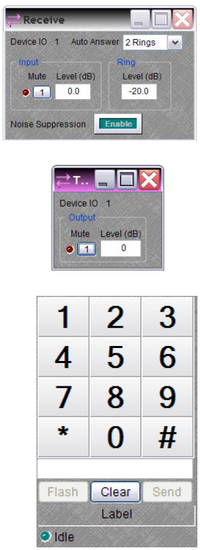
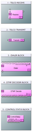
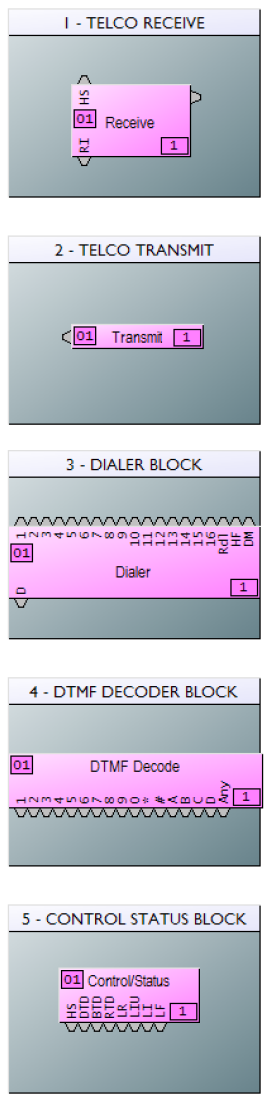
The telephone interface uses the following software blocks:
Receive
The Receive block controls the far end input signal, ring level, automatic answering of the incoming calls and includes the following logic nodes:
- Hook Switch (HS) logic input to manually control the Hook State: Logic High (1) for OFF hook, Logic Low (0) for ON hook
- Ring Indicator (RI) logic output goes High (1) during an incoming call: a useful feature to warn 3rd party devices. (e.g. a control processor) The signal sent to the far end is controlled from the Telco Transmit block. Controls include Mute and output level adjustment. Note: The output level can only attenuate the signal. If you need to increase the gain of the transmit signal, include a level control block on the DSP chain.
Double-clicking the Receive block produces a control dialog box. The Device IO # indicates which hardware connection is associated with that software block. Auto Answer selects the number of rings (or OFF) for automatic answering of incoming calls. Input provides level adjustment and muting of incoming audio signals. Ring provides level adjustment of the internal ring tone signals for incoming calls. Noise Suppression enables cancelation of telephone line noise.
Transmit
The Transmit block provides an input connection for outgoing audio signals. Double-clicking the Transmit block produces a control dialog box. Device IO # indicates which hardware connection is associated with that software block. Output provides level adjustment and muting of outgoing audio signals.
Dialer
The Dialer block interface includes:
- Dial number and Press Send to initiate a call
- Speed dial for up to 16 numbers (logic trigger also available)
- Hook Flash (See below example)
- Redial the last number (logic trigger also available)
DTMF Decoder
The Dual Tone Multi Frequency (DTMF) Decoder block decodes dual frequency tone signals sent over the line (e.g. 1, 2, 3..etc). The logic outputs go high (1) whenever the corresponding DTMF tone is decoded. For more specific application, see the “Advanced Programming” section.
Control / Status
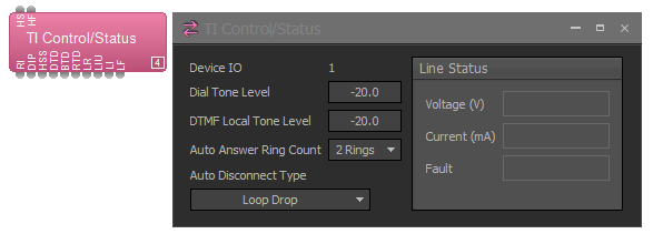
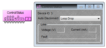
The Control / Status block has multiple features useful to monitor the telephone interface, including:
- Four Auto-disconnect modes:
- None
- Loop drop
- Call progress
- Loop Drop + Call Progress
- Monitoring of the interface is also easily achieved using the multitude of logic outputs. e.g. a command string block connected to the Hook State (HS) logic output could monitor the hook state and indicate its status to the control processor without having to constantly poll the DSP.
- Voltage and Current monitoring are useful troubleshooting tools to test your telephone line. The typical voltage on POTS/PBX lines varies but one should expect between - 54V to - 40V when ON Hook (no dial tone) and –20 to –5V when OFF Hook. Current when ON Hook should be 0mA, when OFF Hook it should be around 23 to 35mA. Currents above 40mA can damage equipment over time. If the card is unplugged it will report a Line Status "Under Voltage" fault in both the Dialer and Control/Status blocks.
- The Control / Status block provides several control output nodes: HS indicates hook switch OFF condition; DTD indicates dial tone detected; BTD indicates busy tone detected; RTD indicates ring tone detected; LR indicates line ready (connected); LIU indicates line in use (by other extension); LI indicates line intrusion (by other extension); LF indicates line fault condition (may require service).
-
Double-clicking the Control / Status block produces a control dialog box. Device IO # indicates which hardware connection is associated with that software block. Auto Disconnect provides three methods of call termination (the method used depends on the far-end equipment). Loop Drop detects interruptions in the current of the telephone circuit, Call Progress detects a special tone indicating call termination, and some far-end equipment may use a combination of Loop Drop + Call Progress.(Note:Auto Disconnect reliability may be affected by intermittent line interruptions or cellular calls.) Line displays voltage, current, and fault conditions on the line.
Useful ATP strings
Hook Flash
Hook Flash is a quick Off/On/Off-hook cycle used to request a new phone line extension to initiate a multi-party teleconference call. It can be activated by a Logic Low(0) to High(1) transition on the HF node of the dialer block or using an ATP command.
Example: Hook Flash the dialer in Device 1 at instance ID 25.
Result: FLASH 1 TILINE 25<LF>
Note: Hook Flash duration is a PABX/PSTN setting that may be adjusted from the property sheet of the Control Status block.

Caller ID info
Providing Caller ID is supported, this command will return a response with: “Call time”, ”Call number”, “Caller”. The TICID attribute will only return the “Call time” and “Call number”.
Result: GET 1 TICIDUSER 25<LF>

See the Audia or Nexia help files for more information about these commands.
DTMF Decoder block
The DTMF decoder block may be one of the best kept secret of our DSP platforms!
Using DTMF tones and a bit of your creativity, you can easily control an AudiaFlex or Nexia TC from a simple telephone handset. The following examples will better illustrate some typical applications. You can download the template design here.
Example 1: Remote control of a DSP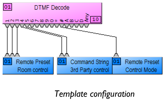
Say for example an end user requires to remotely control the state of a unit using a telephone (e.g. Reconfigure the unit prior to a meeting). Using a bit of logic and some remote presets, one could easily implement the following:
- Call the phone extension connected to the AudiaFlex/Nexia TC unit
- Once connected (Auto-Connect feature), control muting of the unit
- By pressing “# + 1” to Mute the System (recall first preset)
- By pressing “# + 2” to Un-mute the system (recall another preset)
Note: If the telephone interface is also to be used as a local phone, make sure to implement safe proof logic design to prevent false triggering a preset during a call. (e.g. Dial 1800 number and your system goes muted because of the 1 recalling a preset )
In a similar scenario, remote control of third party devices connected via RS232 (e.g. Turn Projector ON/OFF) is easily achieved using a command string block.
Example 2: Phone Paging
End users may want to make use of the existing telephone infrastructure to be able to page from anywhere in the building. Using a combination of DTMF tones and remote presets, it is once again a simple task to program such system. The downloadable template .dap file illustrates a phone paging system meeting the following system requirements:
- Call the telephone extension to page on the system. The auto-connect feature lets you control the paging system.
- There are 8 ceiling speaker zones - addressable on a per zone and "Page to All" basis
- Press “1” to page to zone 1, Press “2” to page to zone 2...etc and Press “9” for Page to All
- Once the page selection complete, press # again to start the page
- Auto-disconnect at the end of the page or press # to end the page.
See the template design for more details. If you ever have questions on how to achieve such system or just need more details to understand this design, don’t hesitate to contact the Technical Support team.
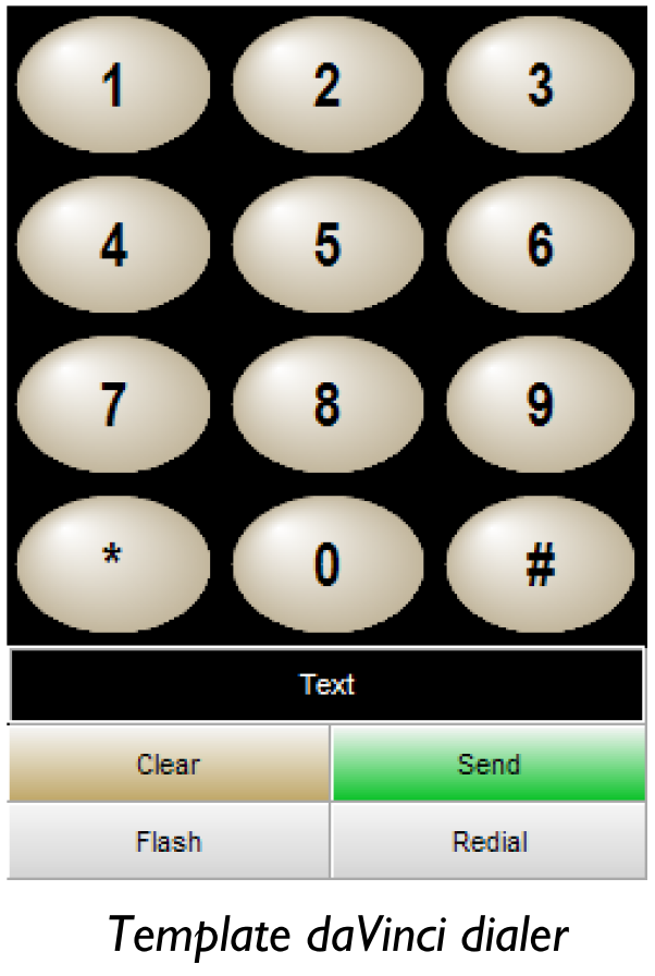
daVinci dialer and third-party control
In most applications, end users would control the telephone interface from a daVinci panel or through a third-party control processor (e.g. touch panel). Both scenarios are very simple to implement.
Biamp daVinci
Programming and control of the dialer interface from a daVinci panel is only few clicks away. Once the file compiles, simply copy and paste the dialer block to a daVinci design to gain control over the dialer. The GUI may also be customized from a multitude of display settings available in the property sheet.
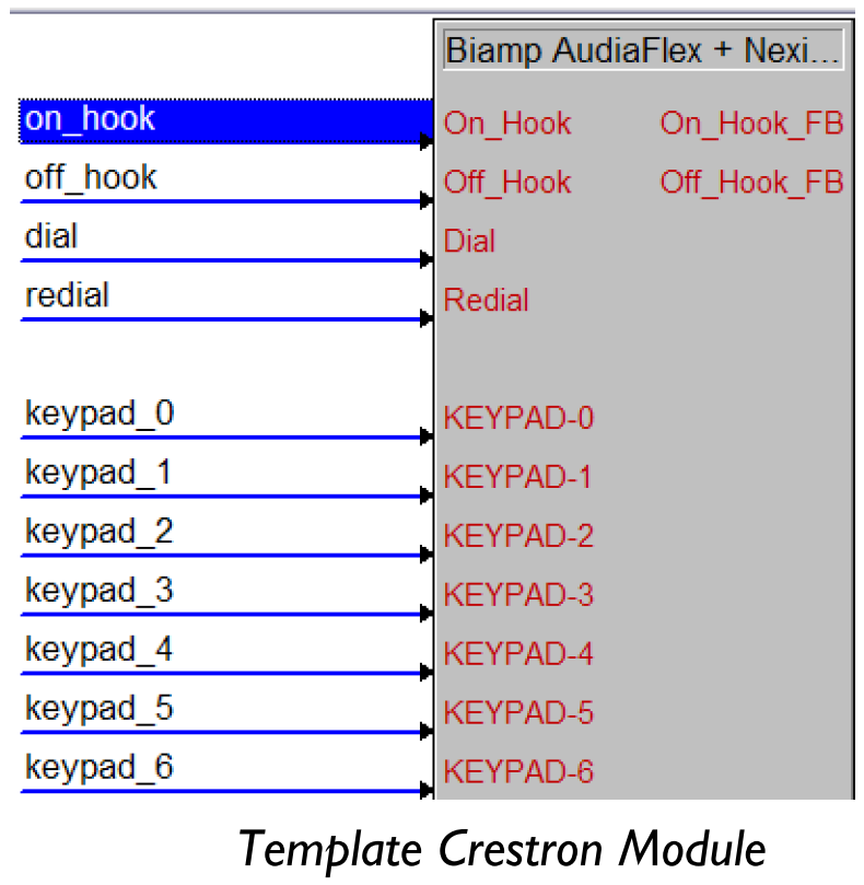
Third-party control
Using our third-party protocol, control of the telephone interface only requires a couple of intuitive commands:
e.g. Dial +1 800 826 1457 for dialer Instance ID 20 in unit 1 would be:
DIAL 1 TIPHONENUM 20 18008261457<LF>
A full featured Crestron Module is available on the Crestron website while AMX programmers can easily implement these commands in their design using our NTP/ATP protocol.
Instance ID Tags
The Instance ID Tag feature was introduced in Audia(v4.3), Nexia software (v2.2) and daVinci(v1.6) for units running firmware version x.460 and up (Audia and Nexia platforms), giving programmers the option to manually assign an Instance ID tag (ASCII label) which greatly simplifies system integration by:
- Providing explicit labels, instead of numbers, for each of the blocks to be controlled (e.g. “level_out”, “TC_RECEIVE”)
- Implementing unified Audia/Nexia programming standards across multiple projects, (e.g. FADER_OUT for all output fader blocks) will limit the amount of control processor programming required.
- Allowing copy and paste of sections from existing projects to new configurations without worrying about the impact on the control system.
- Implementing templates of daVinci panel designs, able to be used in more than one project
Instance ID tags are set from the property sheet of the block to be controlled. Check the Audia/Nexia help files for more info.
Note: Instance ID Tags can only be, at the maximum, 32 ASCII characters long and cannot start with a number or use the following characters: < > & ‘ “
Examples
The downloadable template illustrates a couple of topics covered in this article, such as:
Typical TI-2 configuration
- Hook state monitoring, Dialing in progress monitoring, Hook Flash control
- Control of Hookstate from a contact closure (e.g. switch connected to Voltage Control Box)
Room control
- Remotely Mute/Un-mute microphones from a telephone
- Remotely control third party device via RS232 from a telephone
Phone paging
- Illustrate a phone paging application using a simple set of DTMF tones