AEC in Tesira
This article describes the DSP elements of Biamp's AEC technology (Acoustic Echo Cancelation) in Tesira and TesiraFORTÉ.
Acoustic Echo Cancelation is used to eliminate echo signals that occur naturally in teleconferencing and videoconferencing systems.
AEC blocks
Acoustic Echo Cancelling (AEC) inputs provide support for distance conferencing applications. The AEC functionality is comprised of an input block, an AEC processing block and a reference block. All three blocks must be in the same partition.
- AEC Input - Contains the microphone pre-amp settings for the input; has one output node per channel.
- AEC Processing Block - The AEC processing block has the signal processing functionality; one input and output node per channel.
- AEC Ref - The AEC Reference block is used to tell the AEC process what signal to remove from the mic input; either 1 input and 1 output node or 1 input node per channel (user defined).
Initialization properties
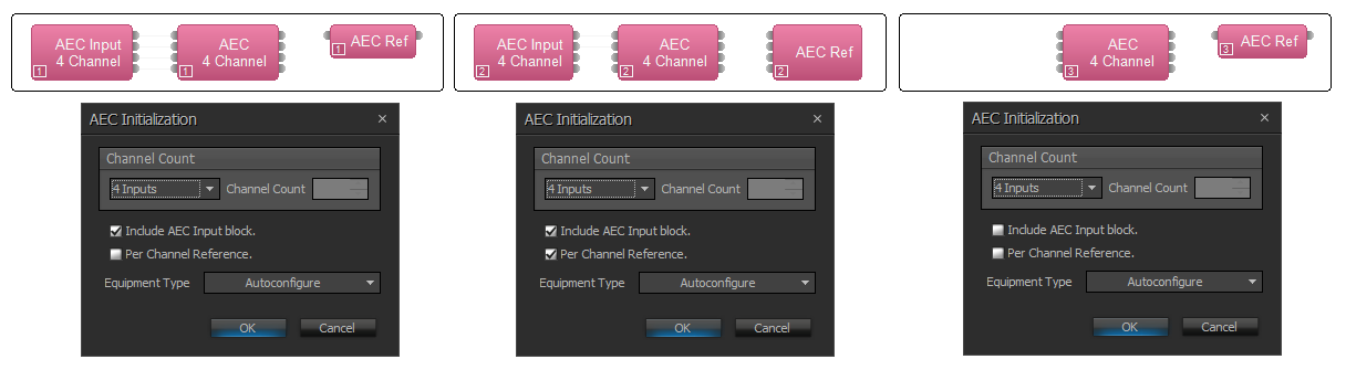
There are several options available when you add AEC inputs to a system:
- Include AEC Input block
- For normal applications, this box will be checked and lines will be drawn linking the AEC Input and AEC blocks. Optionally, in Tesira, the AEC block can be linked to other non-AEC input cards (such as those in an EX-MOD) for a remote AEC solution, while leaving the associated SEC-4 analog input available as a standard input. It is just a matter of connecting lines to the desired input block. All of the components must be in the same partition for this to work. If you know you will not be using the analog input of the SEC-4 you can choose to add AEC without including the AEC input block by leaving this box unchecked.
- Per channel reference
- Checking this box creates an AEC Reference block with discrete inputs for each mic, allowing you to send a different AEC reference selection to each mic's AEC circuit. This may be useful in mix-minus (locally reinforced) systems. If "Per channel reference" is not selected the AEC reference block will have a single input that distributes the same signal to all of the AEC inputs associated with that block. Note that you need to connect an audio object to the output of the AEC Ref block for it to compile. The expectation is that it will be placed in line with the room loudspeaker output feed. If your layout gives the reference its own path, connecting an audio meter to the AEC Ref output will allow it to compile.
- Equipment Type
- When the AEC Input block is selected from the Object Toolbar, an AEC Initialization dialog is produced. Users can choose Autoconfigure to allow the software to automatically allocate it to hardware, or choose to manually assign it to a Server, Rack-mount Expander (EX-MOD with EEC-4 card), or Remote Expander (EX-AEC). Note: If you wish to specify a TesiraFORTÉ for AEC inputs, you must choose the desired model from the TesiraFORTÉ hardware list rather than selecting the AEC Input I/O block.
AEC processing block

- Device IO (x.y) indicates which physical hardware output is associated with that software channel, where x indicates which card slot and y indicates which channel on the card. ?? indicates it has not yet been compiled, or has been manually unassigned from a card in the DSP Properties.
- AEC enables and disables the AEC processing.
- NLP Level optimizes the operation of the Non-Linear Processing (NLP), which is a stage of signal processing post-AEC, and is designed to eliminate any residual echo that may remain after the AEC adaptive filter. The following NLP Level settings are available: None, Low (set by default), Medium and High. NLP is active when either AEC or Noise Reduction are active.
- Noise Reduction is intended to reduce steady-state background noises, such as HVAC systems, fans, motors, or other mechanical devices, that may be picked up by the conferencing microphones and transmitted to the far end. Possible values are Off (set by default), Low, Medium and High. Use the lowest setting that achieves the desired level of background noise reduction. If you hear digital artifacts when the Noise Reduction is used (especially on Medium or High settings) - lower the mic input gain level until artifacts go away.
- Mute turns the input signal on/off.
- Level adjusts the relative input volume.
- Invert reverses the polarity of the input signal.
- Each channel of AEC has a Ch Processing button, which opens up a control dialog window.
- The Copy channel x values to all channels dialogue allows the Tesira user to quickly apply values of a chosen channel to all AEC channels in the block. This handy feature is available in Tesira 3.13 and later.
Channel Processing
Meters

The Meters tab gives information about how the AEC process is functioning.
- AEC Reference shows the signal level at the channel's AEC Reference input.
- AEC Input shows the signal level at the AEC input.
- AEC ADF Output shows the signal level at the output of the adaptive filter (ADF) that performs most of the echo cancellation. This should report a somewhat lower signal level than the AEC Input, since some signal components will have been removed.
- NLP shows the signal level after the Non-Linear Processing filter (NLP Level settings).
- Noise Reduction shows the signal level at the output of the Noise Reduction Filter.
- ERL (Echo Return Loss) shows the difference in level between program material arriving at the AEC reference and that same program material arriving at the AEC input after having been introduced into a physical space via amplifiers and speakers and picked up by the microphone. Since the signal components will be attenuated somewhat by air absorption, ERL will normally indicate a positive value. If ERL is negative or too positive, it may indicate a gain structure problem. A value between 0 and +15 is optimal.
- ERLE (Echo Return Loss Enhancement) shows the amount of echo reduction the AEC adaptive filter is doing. It is the difference in level between echo components arriving at the filter's inputs and the residual echo remaining at the output of the filter. Higher values on this meter indicate that the AEC processing is doing more echo reduction.
- AGC (Automatic Gain Control) shows the amount of gain or attenuation being applied to the input signal by the Automatic Gain Control.
AGC
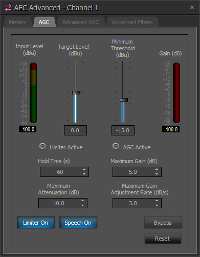
- Input Level meter shows the level of the input signal.
- Target Level defines the signal level that the AGC block will constantly strive to output. If the input level is higher than the target level, the AGC block will subtract gain. If the input level is lower than the target level, the AGC block will add gain.
- Minimum Threshold is the minimum input signal level required for the AGC to make adjustments. If the input signal level is lower than the minimum threshold, the AGC block will temporarily suspend gain adjustments.
- Gain shows how much gain is currently being added to or subtracted from the input signal.
- Limiter Active will light when the clip limiter is actively engaged in preventing clipping.
- AGC Active will light when the AGC block is making a gain adjustment.
- Hold Time is the number of seconds that the AGC block will hold the current Gain setting while not receiving a qualifying input signal. After the Hold Time elapses, the AGC block will reset the gain to zero.
- Maximum Gain defines the maximum amount of gain that the AGC block will add to the signal.
- Maximum Attenuation defines the maximum amount of gain that the AGC block will subtract from the signal.
- Maximum Gain Adjustment Rate defines how quickly the AGC block can adjust the gain, specified in decibels per second.
- Limiter On/Off turns the clip limiter feature on or off. When the clip limiter is on, the AGC will temporarily reduce the gain applied to the input signal if that gain would have caused the signal to clip. Gain adjustments made by the clip limiter may briefly exceed the Maximum Gain Adjustment Rate as necessary to prevent clipping.
- Speech On/Off turns SpeechSense™ technology on or off. When Speech mode is on, the AGC analyzes the input signal to determine if it is human speech. Non-speech signals will not cause the AGC to adjust the gain when Speech mode is on.
|
Qualifying Input Signals The AGC block will only adjust its gain when it receives a qualifying input signal. The definition of a qualifying input signal depends on whether Speech mode is on or off. When the input signal is not a qualifying signal, the AGC block will hold its previous gain setting until it receives a qualifying signal or until the Hold Time elapses. When Speech mode is ON, a qualifying signal must satisfy ALL of the following:
When Speech mode is OFF, a qualifying signal must satisfy the following:
|
Advanced AGC
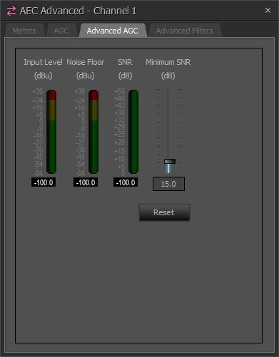
- Input Level shows the level of the input signal.
- Noise Floor meter shows the estimated level of the noise floor of the input signal. The Noise Floor is used in calculating the Signal-to-Noise Ratio.
- SNR meter shows the Signal-to-Noise Ratio of the input signal. This is equal to the Noise Floor level subtracted from the Input Level. In general, the closer the talker is to the microphone, the higher the Signal-to-Noise Ratio will be while they are talking.
- Minimum SNR determines how high the Signal-to-Noise Ratio (SNR) must be before the AGC will make gain adjustments. If the SNR is below the minimum, the AGC will temporarily suspend gain adjustments.
Advanced Filters
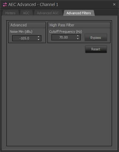
Noise Min – when the level of the signal at AEC input falls below this value, AEC will stop updating its filter. This setting is particularly useful for microphones with a mute button. If AEC still updates filter on a muted microphone, this may result in some echo being heard for a finite amount of time after the microphone is unmuted, while AEC filter updates its values. The Noise Min value can be set between the levels of microphone signal in muted and unmuted state to prevent AEC from updating its filter on a muted microphone.
High Pass Filter is a filter that attenuates input signal components below a programmable Cutoff Frequency. Values in the range of 20Hz to 500Hz can be set. The filter is an elliptic 5th order design which attenuates frequencies below the cutoff at a slope of 30 dB/octave. In most applications a HPF setting between 125Hz and 200Hz will be suitable, with 250Hz realistically being the highest frequency we'd recommend to use. It is important to listen to the mic with headphones to adjust the HPF properly - try to remove as much noise as possible without being destructive to the vocal content.
Tail Length
Tail length describes the time window which an AEC algorithm analyzes in determining echo cancelation.
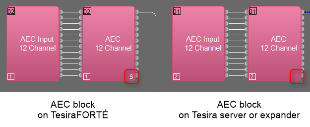
Tesira Server-IO and Tesira Expanders (EX-AEC and EX-MOD) have a 300ms tail length. TesiraFORTÉ devices feature a different hardware profile and support a slightly shorter tail length (250ms) which is suitable for all conference room applications.
AEC block will be labeled with an "S" in the lower right hand corner to denote the shorter tail length, if you:
- Create this AEC block via the I/O Blocks > TesiraFORTÉ menu in ‘TesiraFORTÉ Only’ document mode
- Allocate an AEC block to a TesiraFORTÉ device in ‘Both Tesira servers and TesiraFORTÉ‘ mode
Note that an AEC block created via the I/O Blocks > TesiraFORTÉ menu in ‘TesiraFORTÉ Only’ mode can only be placed in a TesiraFORTÉ device and is restricted to being a 4-channel (for TesiraFORTÉ VT4) or 12-channel AEC block (for all other TesiraFORTÉ models).
Troubleshooting AEC systems
Blocks will not compile
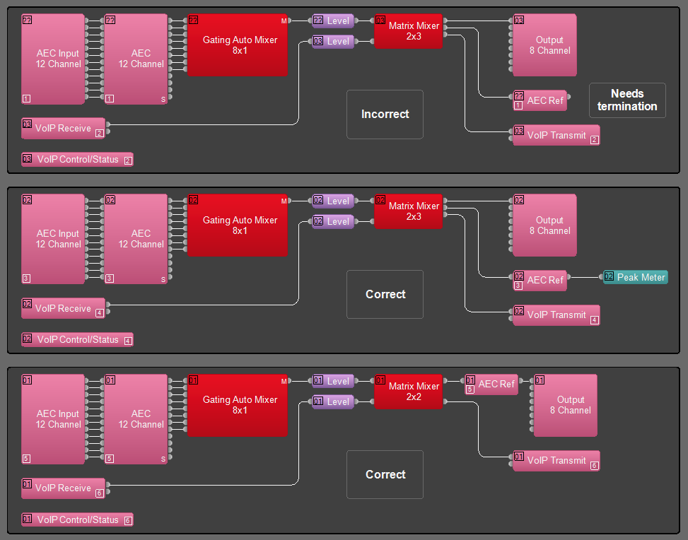
The single channel AEC Ref block requires a termination on its output. By design it would be placed just before the speaker output, but if it is on its own AEC Ref feed from the matrix then it must be terminated. Any blocks in that unterminated path will fail to compile and will have a "??" in the upper left corner rather than a device assignment.
AEC Reference rules
A microphone can never be sent to its own reference.
A mic can be sent to the reference of other mics in mix-minus applications.
Anything routed to the speakers should also be routed to the AEC Reference, and at the same level.
Garbled audio
If audio sounds garbled or "underwater" this is a symptom of a mic which is routed to its own AEC reference channel.
- If other (non-microphone) audio sources are connected through the AEC processing block then AEC processing should be defeated for their channel(s), most critically ensure AEC is off, and NLP is set to None.
ERL values
ERL values are the primary visual indication of correct levels for best AEC performance. They should be observed while the far end is speaking.
- Level controls should be at 0dB in the Tesira.
- Match the gain to the amplifier using the Full Scale Output in the output block to match the input sensitivity of the amplifier.
- Input gain of the microphone should be set so peak values are just passing 0dB on input peak meters.
|
ERL Values |
Most probable cause |
System performance |
Solution |
|
High Values:
BAD |
Microphone input gain is too low. Full scale output to amplifier is too low or amplifier gain is too low. Signal to the AEC reference is too high. Problematic microphone/ speaker placement. |
Average or poor performance results. AEC algorithm may not be able to converge properly. Residual echo and artifacts may be heard. |
Check gain structure - put all level controls at 0dB. Increase microphone input gain. Raise the volume of the amplifier or increase the Full Scale Output level. Reduce the signal fed to AEC reference to artificially lower the ERL. |
|
Optimal Range: ERL between A value between +5dB and +10dB is considered ideal. GOOD |
Acoustic echo loss between the loudspeaker and the microphone is optimized. |
Best performance results |
No modifications required |
|
Low Values: ERL between 0dB and -30dB BAD |
Improper gain structure. Microphone input gain is too high. Speakers are too loud. AEC Reference signal is too low. |
Average or possibly poor performance results. Residual echo is being heard. |
Check gain structure - put all level controls at 0dB. Decrease microphone input gain. Lower the volume of the amplifier or decrease the Full Scale Output level. Increase signal fed to the AEC reference. |
Residual echo
Residual echo can be caused by the round trip latency of the call being too long for the initial echo cancellation filters to handle. It is handled by non-linear processing (NLP). Try next NLP Level settings (i.e. switch from Low to Medium, or from Medium to High) to improve residual echo cancelling by NLP.
Residual echo can also be caused by extremely "live" or reverberant spaces. This can be difficult or impossible to resolve within the DSP settings. In this case a combination of bringing the mics as close as possible to the participants and installing proper acoustic treatments is the best solution. Decreasing the Input Gain for the microphones to limit the amount of reverberant sound they pick up is the next step. Applying aggressive high frequency filtering can help to reduce the amount of reverberant energy as well, but comes at the expense of audio quality. Again, bringing the mics as close as possible to the talkers and installing proper acoustic treatments are the best solution.
- Verify that routing to the AEC reference is correct. Any audio routed to the speakers should also be routed to the reference, and at the same volume it is sent to the speakers.
- A signal should never be routed to only the reference. This will cause AEC convergence errors and audible artifacts.
- If late echo is still heard adjust the NLP Level settings to the next value. If echo is still being heard, switch again (if possible). The settings available are None, Low, Medium and High.
- Install proper acoustic treatment to achieve a properly acoustically dampened space.
- Reduce Input Gain for the microphones. In very reverberant spaces this can help to control the echo sensitivity.
- Apply high frequency filtering for content above 5kHz. This is a last resort for improperly designed rooms.
Sample AEC file
Here is a sample file with 3 partitions which shows a simple conference room, a conference room plus presentation mics, and a mix-minus system. You can use the Persistent Signal Path Identifier to see how the AEC Reference and signal routing is laid out.