Logic Box programming
This article discusses different techniques for programming a Logic Box to perform various common functions, as well as a brief introduction to some commonly used logic gates.
Basics
To program a Logic Box, simply add a Logic Box block to your Audia or Nexia configuration file. The nodes on the top of the Logic Box block represent the physical logic outputs on the device, and the nodes on the bottom of the Logic Box block represent the physical logic inputs on the device.
There are only two states that a logic signal can be: high or low (also frequently referred to as on or off, 1 or 0, true or false). The sections below describe how logic signals interact with the Logic Box’s logic inputs and outputs.
Logic outputs
The logic outputs on a Logic Box are used to trigger contacts to open and close, and can be thought of as being similar to a relay. They are often used to control LED’s or trigger external relays. By sending a logic signal to the top node of a Logic Box block corresponding to the logic output that you wish to control, you can change whether that logic output is creating a short circuit to ground or an open circuit to ground. Sending a low logic signal results in a short circuit, and sending a high logic signal results in an open circuit.
Logic inputs
The logic inputs on a Logic Box are used to detect contact closures from external devices. They are often used to sense closures from external switches or pushbuttons. When a switch connected to a logic input is closed (shorted to ground), a low logic signal is generated at the corresponding bottom node of the Logic Box block. When the switch is open to ground, a high logic signal is generated. This means that logic inputs are “normally high”; that is, if there is nothing connected to a logic input, it will be generating a high logic signal.
Logic gates
Logic gates can be used to transform logic signals in various ways. To insert a logic gate into your configuration file, select Logic Gate from the Control menu on the device toolbar, click in your file to insert it, and then select the type of logic gate you want to use. It’s not in the scope of this document to describe all logic gates in detail, but below are a few that are commonly used with Logic Boxes. For details on other logic gates, consult the Help system in the Audia or Nexia software or the Audia/Nexia user manual.
NOT Gate
A NOT gate is a simple logic gate which inverts the logic signal that it is receiving. In other words, if you send a low logic signal to the input of a NOT gate, it will output a high logic signal, and vice versa.
For instance, if you connect a contact closure button to a logic input on a Logic Box, and that button is normally open (i.e. it creates a short circuit when the button is pushed), then the Logic Box block will be generating a high logic signal when the button is not pushed and the logic signal will go low when the button is pushed. However, you may want the logic signal to be low when the button is not pushed, and high when it is pushed. In this case, a NOT gate is the solution.
Flip Flop Gate
A Flip Flop gate is used to transform a momentary logic pulse signal into a latching (or toggle) logic signal. The Flip Flop gate works by toggling its output signal whenever its receives a low-to-high logic transition on its input. It doesn’t do anything when it receives a high-to-low logic transition. So, the first time it receives a low-to-high logic transition at its input, it will send a high logic signal out of its output; the next time it receives a low-high-logic transition, it will start sending a low logic signal out of its output.
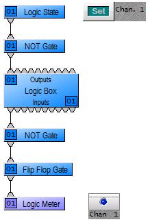
Logic State
A Logic State block is a logic block which generates a logic signal. It will generate a low logic signal if its “Set” button is disengaged, and it will generate a high logic signal its “Set” button is engaged. A common use for a Logic State block is to generate a logic signal and send it directly to the top nodes of a Logic Box block (logic outputs). This would allow you to manually control whether a logic output is opened or closed.
Logic Meter
Logic Meters are a very useful troubleshooting tool when programming a Logic Box, because they allow you to view the state of a logic signal at any point in your logic circuit. You can find Logic Meters in the “Meters” menu in the device toolbar.
Example applications
Contact closure button recalls preset
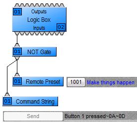 A simple, common application is to connect a contact closure button to a Logic Box, and recall a preset whenever that button is pressed. The key to making this happen is the Remote Preset block. This block is triggered by a logic signal and recalls a preset whenever it sees a low-to-high logic transition. To load a preset into a Remote Preset block, open the block, right-click on the preset button and select “Assign Preset”. Then, choose the desired preset from the drop-down menu. If your contact closure button is normally open, using a NOT gate as shown in the picture to the right will ensure that the preset gets recalled when you push the button down, not when you let it up.
Contact closure button sends a serial string
Also in the picture to the right, notice that the same contact closure button is connected to a Command String block. A Command String block operates the same way as a Remote Preset block, but instead of recalling a preset, it sends a custom string out of the RS232 port on the unit. This is useful for notifying a control system of an event that has happened. You can also use a Command String block to send hex characters by preceding the two-digit hex code with a tilde character (~).
Momentary contact closure mutes and unmutes a mic
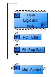
The Mute Control block has the capability of controlling its mute buttons via logic signals. When dropping the Mute Button block into your file, ensure that the “Control Inputs” check box is checked. This will enable logic inputs on the block. If the logic input for a channel receives a high logic signal, it will mute the mic. If it receives a low logic signal, it will unmute the mic.
More often than not, a microphone mute switch is a momentary switch. That is, the switch is closed while you’re pushing it down and open when you let it up. If you connected a momentary switch to a Logic Box, and then connected a logic signal from the Logic Box directly to the Mute Control block, it would only unmute the mic when you push the button down and would mute the mic as soon as you release the button (i.e. a push-to-talk button). If you connected the Logic Box through a NOT gate and then to the Mute Control block, it would mute the mic only while the button is held down (i.e. a push-to-mute button). More commonly, users expect a toggle functionality where the mic will toggle on and off each time they press the button. They might also expect the LED on the mic to turn on when the mic is live and turn off when the mic is muted.
The logic circuit in the picture to the right shows a common way to make this happen. The Flip Flop gate transforms the momentary logic signal to a latching signal, and its output controls both the muting of the microphone and the state of the LED.
Note that a NOT gate is needed before the Flip Flop so that the Flip Flop will change state when the button is pressed rather than when the button is released.
Using multiple Logic Boxes in a system
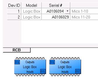
If the application requires a lot of microphones, you may be required to use multiple logic boxes to connect all of them. In this case, it’s important to know how to identify each Logic Box. In each Logic Box block, there is a number in the top-left corner and another number in the bottom-right corner. (If these numbers aren’t there, go to Tools—>Options—>Display tab and select “Display device assignment”.)
The number in the top-left corner tells you which unit the Logic Box is assigned to. This must correspond to the unit to which the Logic Box is physically connected. If it is not set to the correct unit, open the Properties sheet on the Logic Box block, go to the DSP Attributes tab, select the correct unit under “Allocated to Unit”, and select “Yes” under “Fixed In Unit” to ensure that the compiler doesn’t change which unit it’s allocated to the next time you compile.
The number in the bottom-right corner is the ID of the Logic Box itself, and it allows you to identify each Logic Box individually. This number will also show up in the RCB tab of the Equipment Table (Tools—>Equipment Table), and it will allow you to assign the correct serial number to the correct Logic Box.