Voltage Control Box
Analog potentiometer inputs
Potentiometers connected to the Voltage Control Box can be programmed in the software to control various system levels.
On the back of the Voltage Control Box, there are two analog connectors and one logic connector. The analog connectors have 4 pins each. The numbered pins are the voltage inputs while the V is the voltage supply and the down pointing arrow is ground.
The analog inputs support linear taper potentiometers with resistance values between 5kΩ and 50kΩ. The Voltage Control Box's analog inputs can be calibrated to the resistance range of the potentiometer that is connected to it.
Logic inputs
A logic input can provide control of system actions like recalling presets, muting channels, ducking signals, combining rooms, etc by means of an external contact closure or 5V TTL logic.
On the back panel of the Voltage Control Box, there is a Logic connector with 4 logic pins and a ground pin labeled with a down pointing arrow. Also note that these pins are numbered above and below the connector. Logic pins that are being used as inputs are counted from left to right, so you will be looking at the numbers on top to reference the logic input.
Logic outputs
A logic output can be used to provide indication such as microphone activity or control external devices by using relays such as speaker level control.
These logic outputs are “open collector” with an internal pull-up. This means that when not active, they will measure 5V but will not provide current. Upon activation (from a logic signal within the Audia/Nexia program), the logic output goes low, allowing current flow.
Logic outputs are rated at 24V and 500mA of sinking capability.
On the back panel of the Voltage Control Box, there is a Logic connector with 4 logic pins and a ground pin labeled with a down pointing arrow. Also note that these pins are numbered above and below the connector. Logic pins that are being used as outputs are counted from right to left, so you will be looking at the numbers on the bottom to reference the logic output.
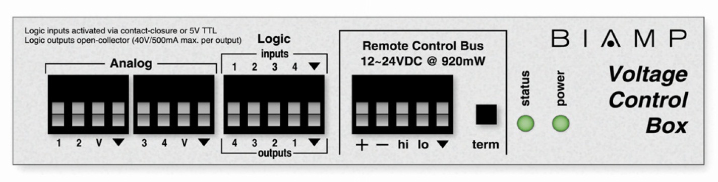
Remote Control Bus
The Voltage Control Box is connected to the rest of the system via the RCB connector block. The details of connecting the Remote Control Bus are covered in Remote Control Bus (RCB) wiring.