AudiaFUSION fault monitoring and failover
AudiaFUSION features a comprehensive suite of amplifier monitoring functions for critical applications. If something goes wrong with your amplifier, cabling, or loudspeaker, AudiaFUSION can detect it and report it as either a warning or an alarm.
Warnings let you know that something is not optimal, but that it isn’t an audio-stopping failure. Alarms indicate that something has failed and audio is not getting to the speaker. Failover, if enabled, is triggered by alarms (see Failover below). Both warnings and alarms are available as logic outputs in Audia software, and therefore can be monitored in daVinci, reported to a control system via RS232, or otherwise indicated via any standard method using logic.
In addition to a battery of internal tests, AudiaFUSION allows the user to set up a sophisticated impedance monitoring system on each output channel. Output impedance can be monitored over four user-defined frequency bands, and a warning can be triggered if the impedance falls outside of the user-defined tolerance.
Front Panel LED’s
AudiaFUSION’s front panel allows you to get a lot of information about the health of the system at a glance. See figure 1 below for a description of AudiaFUSION’s 37 front panel LED’s:
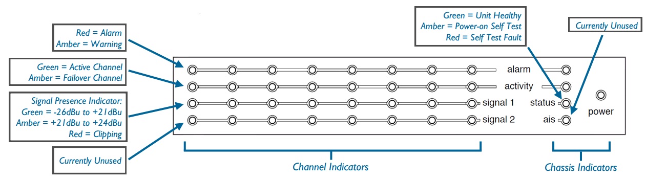
Figure 1 - Fusion Front Panel LED’s
Failover
AudiaFUSION can not only automatically detect a fault, it can do something about it too. When an alarm is raised by AudiaFUSION, it can route audio around the problem in two different ways: channel failover and device failover.
In channel failover mode, an odd-numbered channel can be linked to its adjacent even-numbered channel (i.e. channels 1 and 2). The even-numbered channel acts as a redundant failover channel. If AudiaFUSION detects a failure on channel 1 and raises an alarm, channel 1 is turned off and audio is immediately routed to channel 2.
In device failover mode, an entire AudiaFUSION chassis is linked to another redundant chassis. If an alarm on any channel is raised in this case, all channels on the first chassis are turned off and audio is immediately routed to all channels on the second chassis.
These failover modes require redundant wiring schemes to operate correctly. Since the AM-600 outputs are relay-isolated and only one channel of a failover pair is ever active at a time, primary and secondary channels can be connected in parallel without a problem. See figures 2- 4 below for three examples of redundant failover wiring schemes.
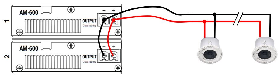
Figure 2. In this example, the failover channel is looped over to the primary channel. This wiring scheme is the easiest and most cost-effective to install, and it ensures audio will reach the speakers in the event of an AM-600 card failure.
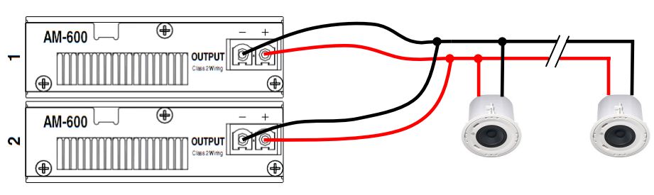
Figure 3. In this example, a separate cable run has been pulled from both amplifier channels to the first speaker in the zone. While this is electrically equivalent to Figure 1, it also protects against a failure in the cabling, especially if different wiring paths are used. Alternately, the secondary cable run could be connected to the last speaker in the zone.
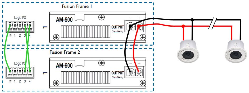
Figure 4. This example shows a wiring scheme for device to device failover. This failover mode requires two Fusion frames with identical card configurations. Note the additional logic connection that is required between frames.