Integrate Biamp Control with Zoom Room's “Room Control”
By following this guide, you will be able to control your ZOOM Room directly via the “Room Control” tab of your Zoom interface, using Biamp Control equipment as a control extension.
Prerequisites for using Room Controls
- Zoom Rooms for macOS or Windows or Zoom Rooms Appliances, version 5.1 or higher.
- A Biamp Impera Uniform or Tango.
- Biamp Project Designer 1.32.2 or later.
- One of the two custom-made "Sample Files" that are available at the bottom of this article.
- Any system needs to be based on these sample files in order for the Room Control feature to work.
How to get started
Download a sample design
Download one of our sample designs at the end of this article, based on Tango or Uniform, that fulfills your connection and control needs.
Any system needs to be based of these sample files for the "Room Control" feature to work.
Add devices to your project
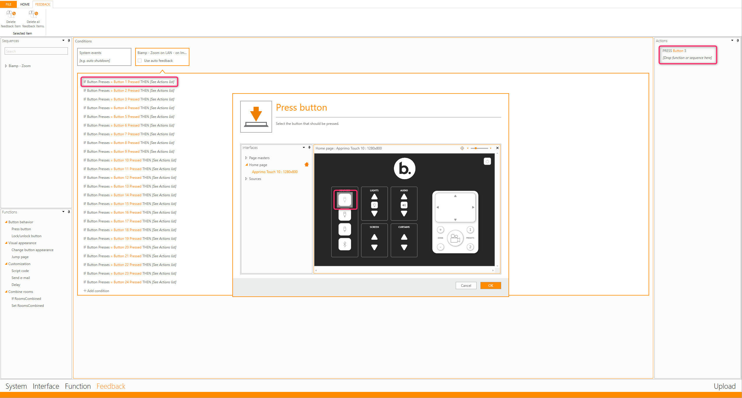
Add the required device drivers to the sample design and associate the sequences with the pre-defined buttons as a normal Project Designer configuration. If you wish to see which buttons in Project Designer will be triggered by each button press from Zoom, visit the Feedback section and view the action of each feedback.
Update the IP settings
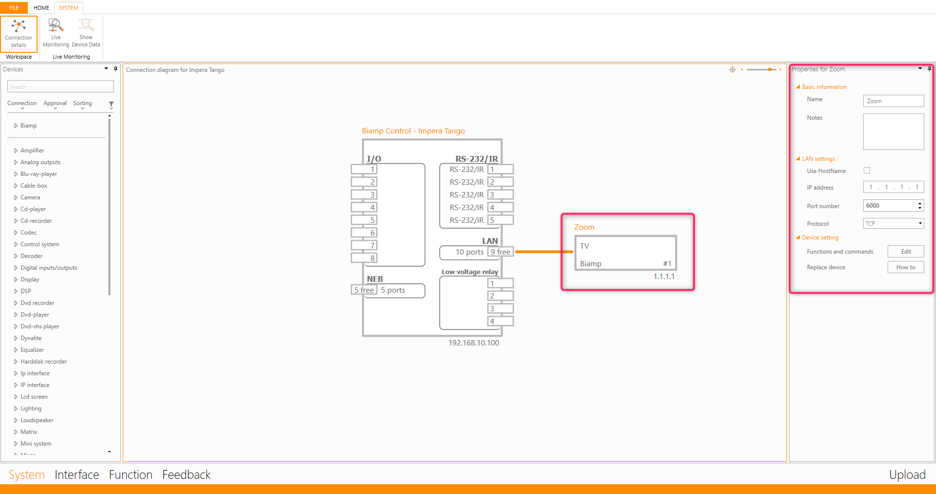
Update the IP address of the Zoom driver to match the IP address of your Zoom Room.
Upload the Design
Upload the design to your Tango or Uniform.
Test the control system to verify functionality
Uniform
To test a system based on a Uniform, use the 8 physical buttons on the Uniform's keypad.
Tango
To test a system based on a Tango, connect to it via Ethernet, open a browser, and enter the IP address of the Tango. This will take you to the WEB UI where you can test the system by pressing the buttons.
Please note that this UI will never be visible to the customer, since they will use the ZOOM interface to control the room.
It’s there for configuration and testing purposes only.
Modify the JSON file
Open the JSON file you received in the “Sample Design” download. Please note that the JSON entries have already been linked to button presses in Project Designer. You can view these within the Feedback section of the sample files.
Assign the Control System IP
Make sure you set the IP address of the "GenericNetworkAdapter" to match the address of your Impera controller. In the Sample Design you've downloaded, the address is set to the default 192.168.10.100. If you change this IP address in Project Designer, you need to change it in the JSON file as well. The IP address is bolded and underlined below:
{
"adapters": [
{
"model": "GenericNetworkAdapter",
"ip": "tcp://192.168.10.100:6000",
"ports": [
Delete any unused sections
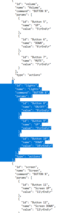
If there are sections you don’t wish to keep in your control system, you can easily delete these entries from the JSON file. In the image below, we've decided to delete the “Lights” control.
Make sure you delete the full section (as marked below) and that the section above ends with "}," and that the section below starts with "{" (if not the last section.
Rename the "name" entries to better match your system
The function entries in the JSON file look like this:
"id": "Button 1",
"name": "HDMI 1",
"value": "1\rEnd\r"
- The entry after “id” (Button 1 in the example above), describes which button will be pressed in Project Designer. Do not change this since it might get confusing.
- The entry after “name” (HDMI 1 in the example above) which is highlighted in bold text above, is the name shown on the ZOOM interface.
- This is information can be changed to better match your system.
- An example of this is that if you are using VGA as an input and have assigned that input to the HDMI 1 button in Project Designer,
- you can preferably rename the “HDMI 1” entry to "VGA".
Further Modifications
If you wish to learn how to customize the JSON file further, please follow the link below:
Room Controls for Zoom Rooms – Zoom Support
Enabling Room Controls in your Zoom Room
To upload your JSON configuration profile to the Zoom Room, please follow the steps below:
- Sign in to the Zoom web portal.
- Under "ADMIN" Click Room Management, then select Zoom Rooms.
- Select the name of your Zoom Room.
- Select Room Settings.
- Under Devices, toggle Enable Room Controls to on (blue).
- Click Create Profile.
- Enter the JSON configuration for this room.
Test the Room Controls
Now you can test the room controls via the Zoom Interface by pressing the Room Controls icon:
.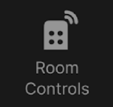
Please note that this icon will populate your Zoom Room Controller interface automatically. It will not be visible on the main Zoom Room interface.
An example of the differences between these: If you host a Zoom Room on a laptop or NUC and connect an external touch display to control it, this display will be running Zoom Room Controller and give you access to the Room Controls-feature.
If you instead connect a normal display to view Zoom Room-host, you will view the standard Zoom Room-application and will not be able to use Room Controls.