How to use a GPIO as Input
You can use one or more of the IO's as an Input in order to trigger any sequence or event in Biamp Project Designer. It might be an external button, switch, PIR motion sensor, or partition sensor which enables an event in the controller, like combining two rooms and locking buttons in the secondary room.
An input can trigger in two different ways, high or low.
- Input trigger low: < 1VDC
- Input trigger high: > 4VDC
In the schematic below, you can see that the controller accepts voltages up to 24 volts and a short to ground.
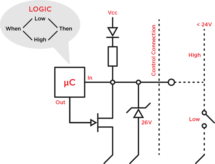
The schematic above is the inside and outside of the input circuitry. In many cases you will need a pull-up resistor to not have a floating pin (input) because a floating pin is susceptible for electromagnetic influence and therefore you might get unwanted behavior on the input.
Watch this wikipedia article if you wish to know more about using a pull-up resistor
In the Systems page of Project Designer you assign one of the IO's as an Input as shown below:
Then go to the Feedback section and give the input a function as shown here:
Application & Troubleshooting
GPIO inputs on Impera units have a floating 3 VDC to register a “high” logic state inside of Impera. When connecting a 3rd party input device that outputs a dry contact closure, this can be wired directly into an Impera GPIO unit and will pull the voltage down to a “low” state (< 1VDC) when the contact is closed. This gives independent “high” and “low” states for programming inside of Project Designer.
If the 3rd party input device is only capable of providing voltage when in a “high” state, a pull-down resistor wired in parallel to the input will be required to pull the floating 3 VDC provided by the Impera GPIO down to < 1VDC when the 3rd party input device is in its “low” state and not outputting voltage. When the 3rd party input device is “high” state and outputting voltage, VDC at the GPIO input should measure > 4VDC.
Remember that the GPIO input is looking for voltages above or below the following thresholds:
- Input trigger low: < 1VDC
- Input trigger high: > 4VDC
When in doubt, use a multimeter to measure the output of the switch or sensor and document the findings. Then connect the switch or sensor to the GPIO and take the measurements again. In some applications, the sensor output may not pull the circuit down below the 1VDC threshold. If this is the case, a resistor can be added to the circuit in series or parallel with the sensor. Measure and test until expected functionality is achieved.
24VDC is a common sensor logic output used as the 'High' output; when connected to the GPIO of an Impera controller, the 'Low' output may only pull down to 3VDC. This will not pull down far enough to trigger the 'Low' so applying a 4.7k or 10k ohm resistor to the circuit will change the measured 'High' and 'Low' to operate within the proper range.