Webex Room Navigator integration
Biamp and Cisco play well together
In Project Designer 1.25 we made a great integration between the two. So all you need on the conference room table, is the Webex Room Navigator (wall or table version) to control all the lighting, heating, screens, projectors, displays etc.
The predecessor to the Webex Room Navigator that was launched in 2021, was the Cisco Touch 10 display and that is what the integration was built for, but it is compatible in exactly the same way with the Webex Room Navigator.
The brain behind all the peripheral control can be either a:
- Sierra II
- Lima
- Tango
- Alfa II
The idea is that you design the UI for your specifications inside the Cisco In-Room Controls and then export it to a file, a file which is easily imported into Project Designer.
After import, you simply just link the buttons to the similar UI you have created in Project Designer.
The supported devices working in conjunction with the Webex Room Navigator / Cisco Touch 10 are as follows:
-
SX series: SX10, SX20, SX80
-
MX series: MX200 G2, MX300 G2, MX700, MX800 Single, MX800 Dual
-
Webex Room System series: Room 55, Room 70 Single, Room 70 Dual
-
Webex Room Kit series: Room Kit Mini, Room Kit, Room Kit Plus, Room Kit Pro
-
Webex Board series: Webex Board 55, 70 and 85
-
DX series: DX70 , DX80
-
Desk Pro
How it is done, the walkthrough:
Setting up a serial connection from the Cisco system
We recommend using a USB->Serial (RS232) converter with the Cisco systems. By using serial connection, you also get rid of the potential issue of putting the control devices on the same secured network as the Cisco devices are on. We have a USB>Serial device that we have tested, available here, but in theory most types should work.
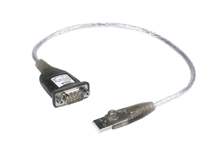
When the USB->Serial device is connected to the Cisco USB port, make sure to reboot the Cisco codec.
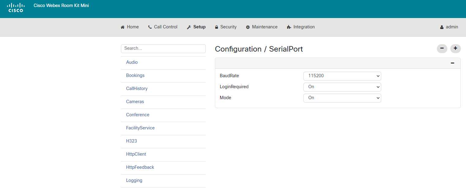
Then configure the serial settings in the Cisco device under 'Setup > Configuration > SerialPort'.
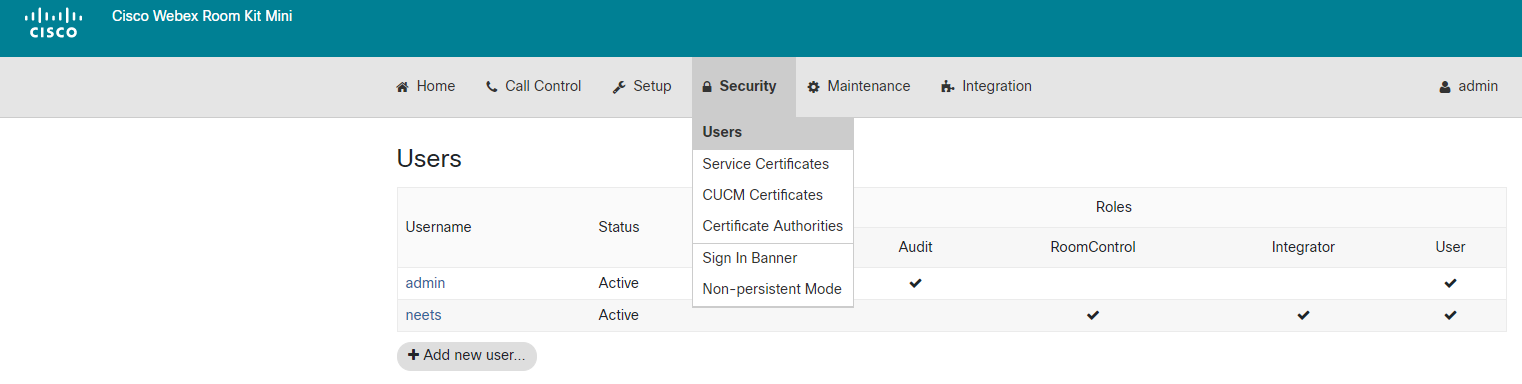
Creating a user
Best practice is to create a user for the control system that has access to control the codec. Do that under Security > Users. This username and password should be entered later in Project Designer, so please take note of this. Enable the same features as shown below.
Creating the UI in Cisco
Using the In-Room Controls is very easy, simply create the panels and pages you need and equip them with the buttons and sliders for the control
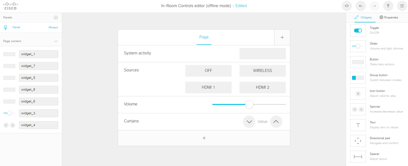
After you are done creating, just export a file we can import into Biamp Project Designer.
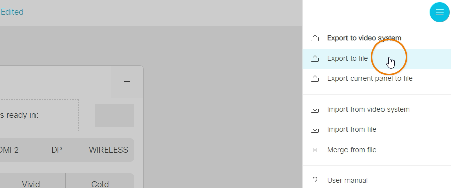
You can do that from the burger menu on the top right corner and press "Export to file".
Creating the UI in Biamp Project Designer
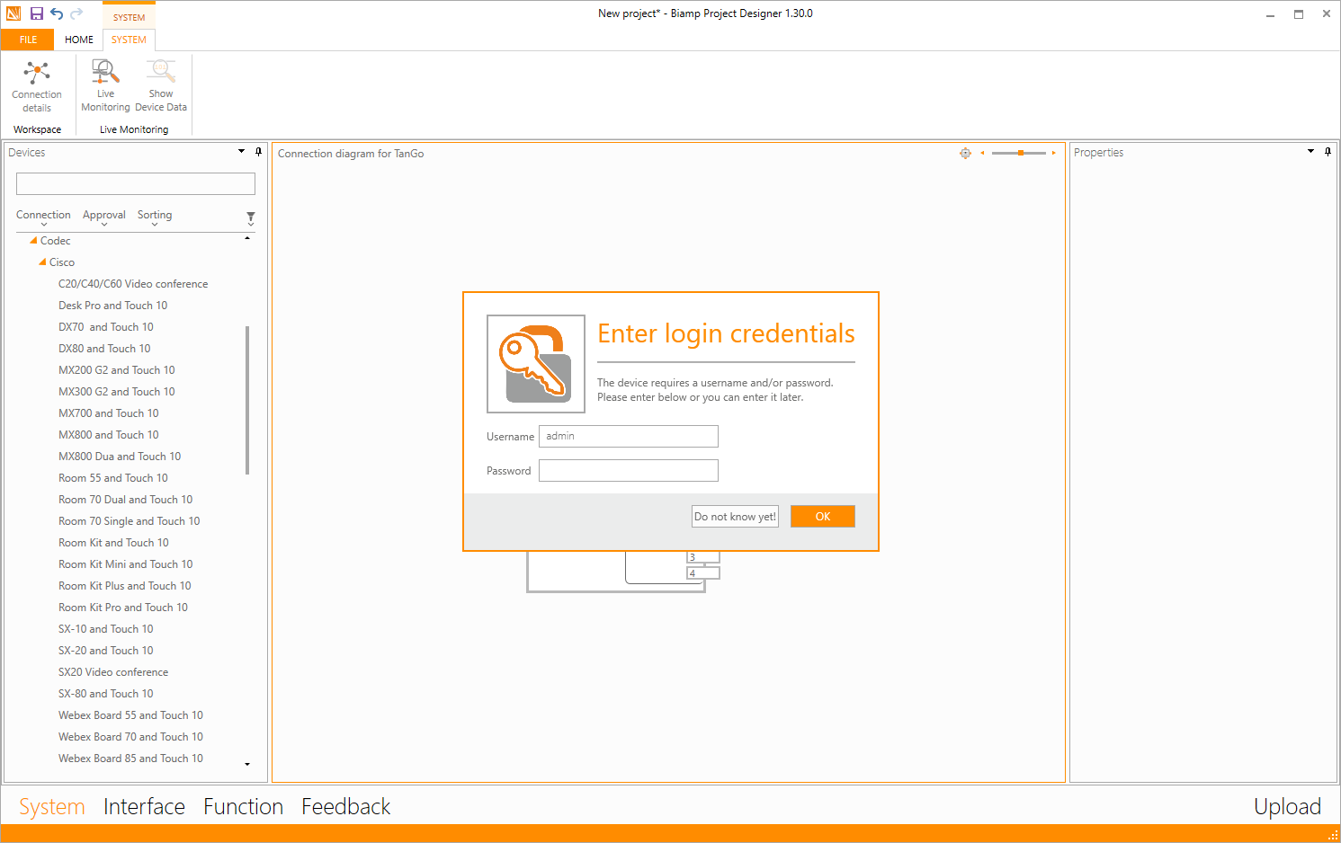
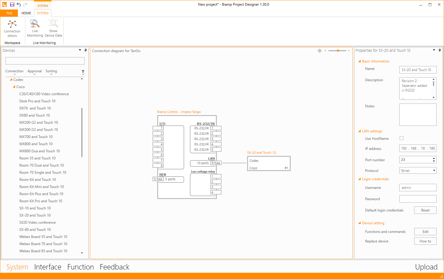
In the Project Designer System view, choose the codec and connection type that you have chosen for the install. Serial (RS232) and LAN connection are the possible connection types for the Cisco codecs, but as mentioned above, not all codes support a Telnet connection.
You will get pop-up boxes with the timings and password, and if you are using LAN, then make sure the IP address for the Codec is correct, and of course make sure to set the IP in the Codec as well.
Then add all of the peripherals that you wish to control, displays, amplifiers, curtains etc.
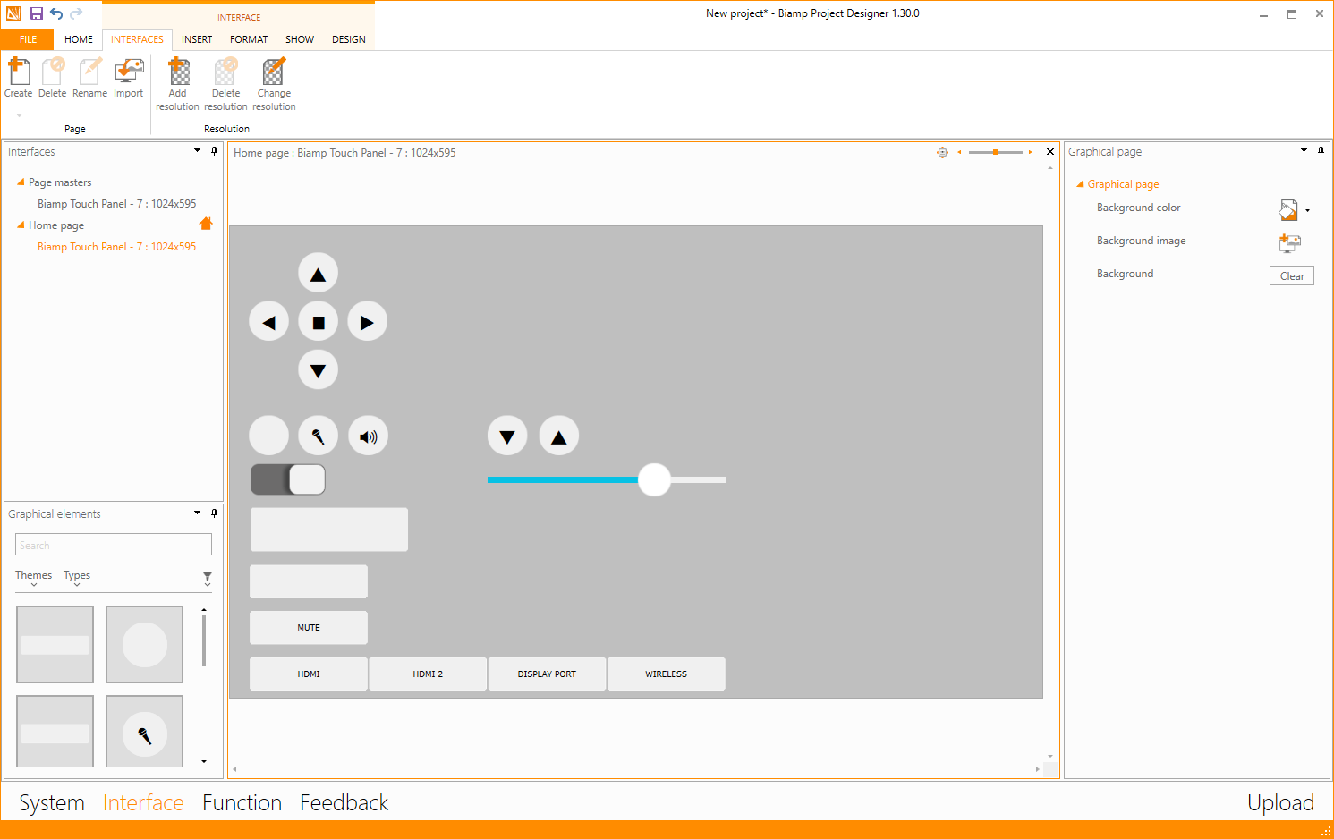
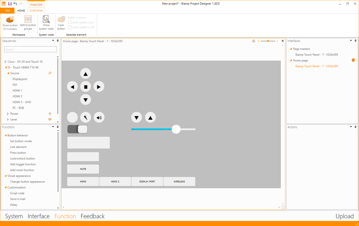
In the Interface section we have created a UI theme called Cisco Touch 10, which makes you able to resemble what you created in the In-Room Controls.
In the Functions section it is business as usual, simply just drag the sources, levels and controls onto the buttons.
The biggest difference to the usual approach is to be found in the Feedback section, where, when you select the Codec can see several new buttons and things to learn. Let's have a closer look!
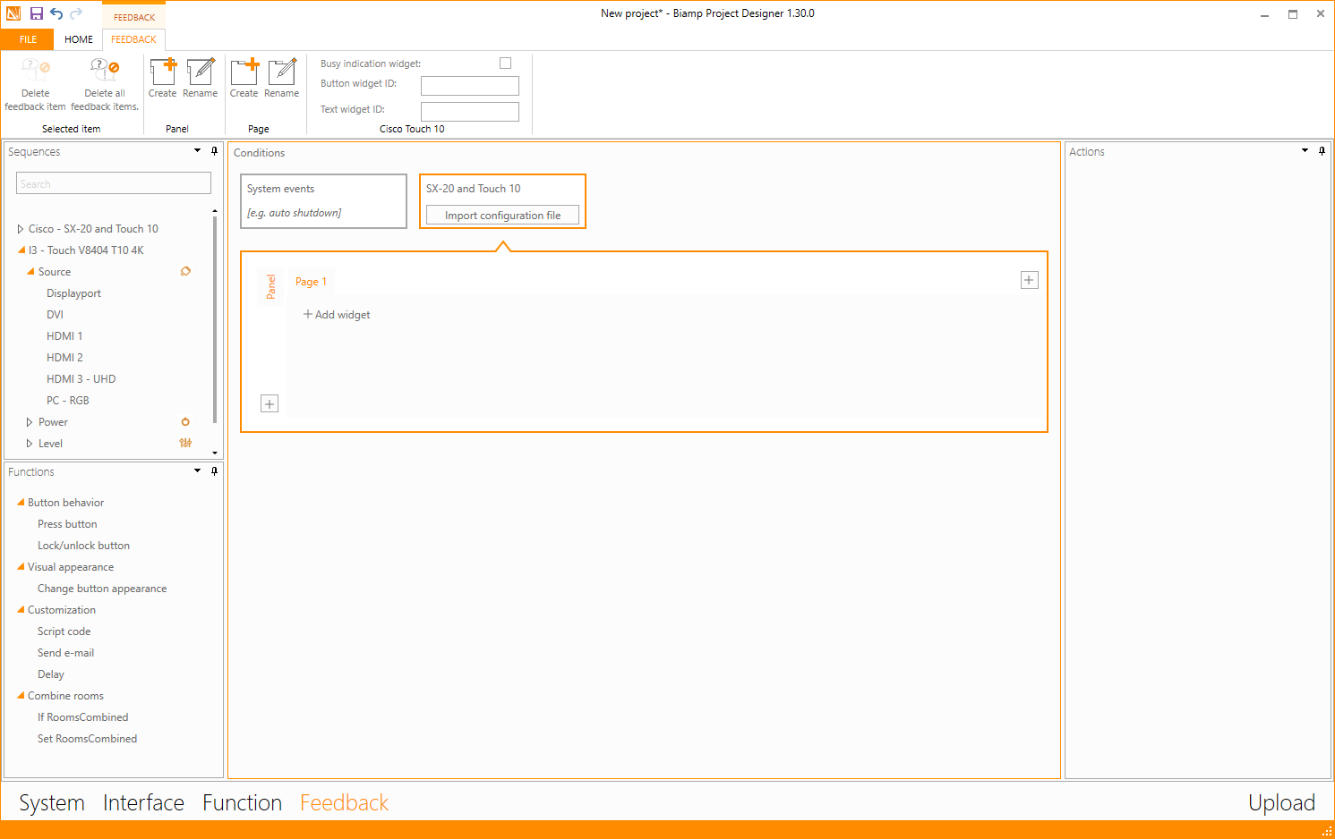
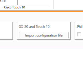
The easiest way to get started is to import the file we exported in the Cisco.
Simply press "Import configuration file" and select the file (Cisco drops the file in your Downloads folder)
After import you will see that the panels and pages created in Cisco In-Room Control is now shown below in the orange box:
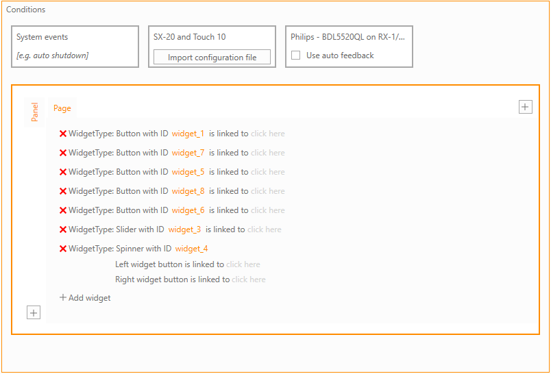
Now it is time to link the different widgets to the buttons in your project file. This is done by pressing the "click here" to the right of each line.
Each button in the Cisco is given a widget ID, which can be seen by pressing the different buttons in the In-Room Control.
In the below example the OFF button is widget ID number 3 (widget_3)
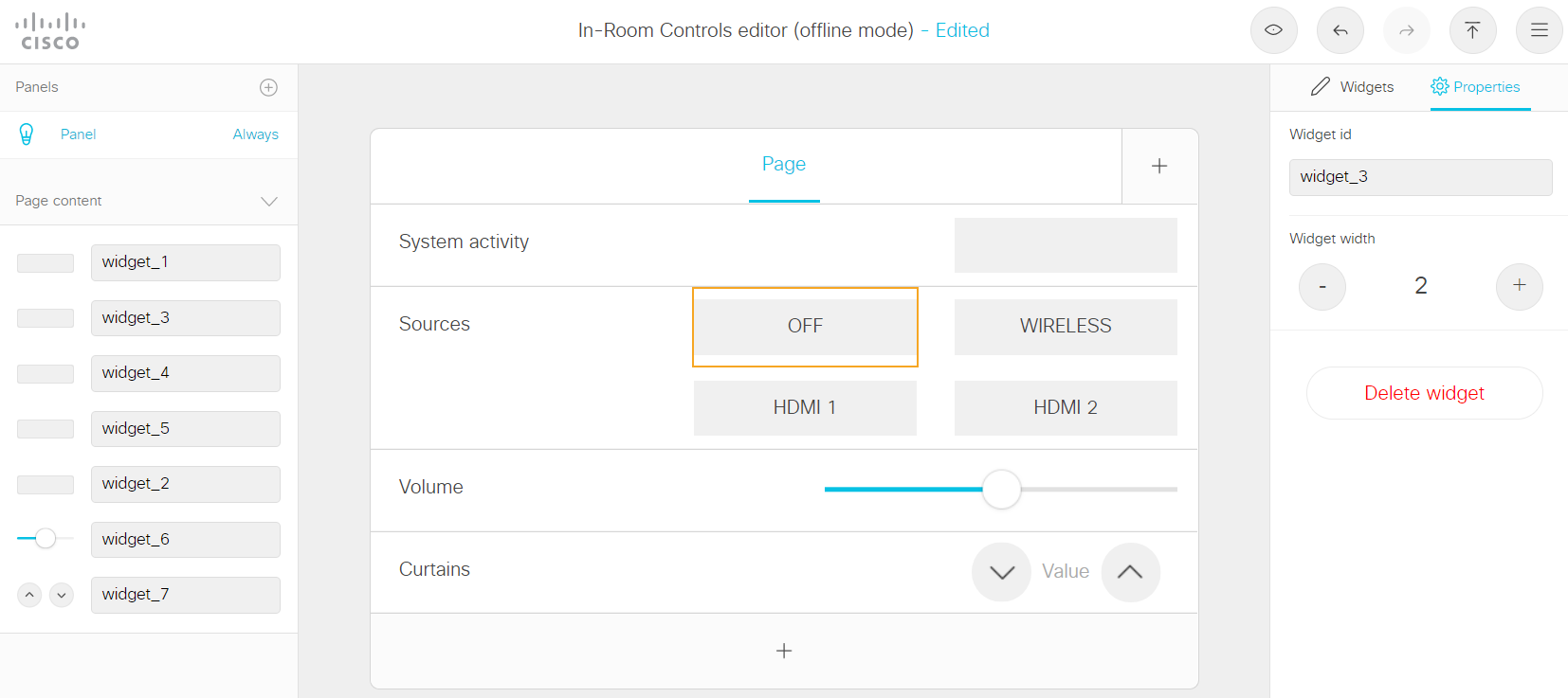
So simply link this to the OFF button in the Biamp project and repeat on all the other widgets/buttons.
System activity
In the Biamp integration with Cisco Touch 10, it is possible to get an activity status shown on a button, in this case it is the buttons on the top of the UI. This gives the users a helping hand on showing that the system is performing activities and therefore cannot be pressed at the moment.
It is possible to show both a button that blinks and/or a text with countdown.
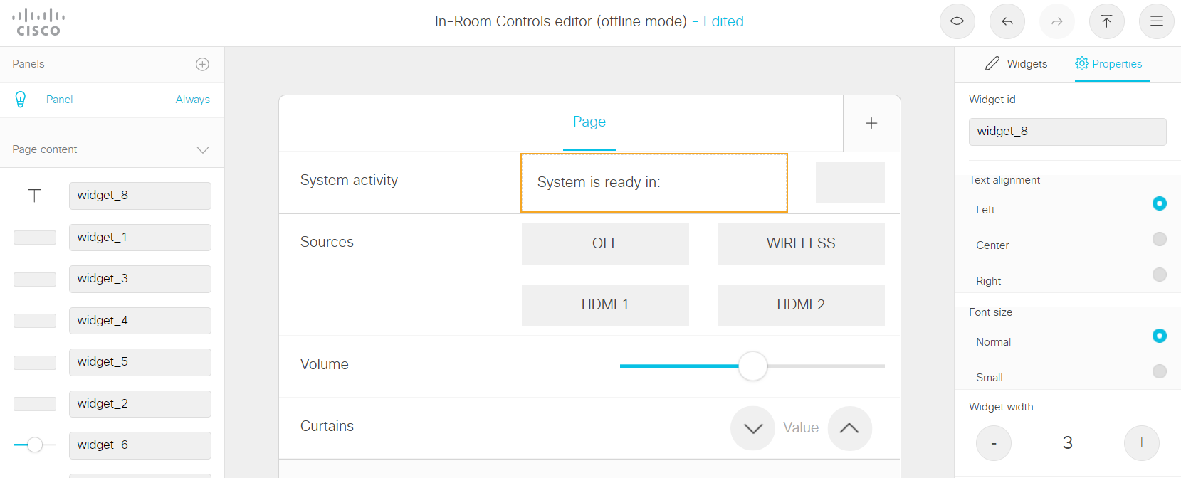
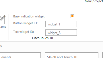
To link these buttons, you will need to connect the button and/or the text in the In-Room Control.
This is done in the top of Project Designer as shown below, just remember to mark the bullet "Busy indication widget" to be able to write in the boxes below:
When you have done all of the above, your system is ready to deploy, all that is missing is to upload the project file to the controller.