QtPro pendant-mount emitter installation
The Pendant mount is an accessory used to install Qt Active or Standard Emitters in an open or raised ceiling space and suspend them at the optimum height for best coverage.
The mount ceiling box cover is designed for use with a standard 4” octagonal electrical ceiling box at the suspension point. The electrical box and the emitter are not included in the pendant mount package and must be purchased separately.
The included cable is 20 feet (6 meters) long and is specially selected to suspend the mount while providing the necessary connections to the emitter.
Product specifications and included components
Specifications
- Height: 7” (17.8cm)
- Diameter: 3.3” (8.4cm)
- Hanging Weight: 12 oz. (340g)
- Material: ABS and Polypropylene (except cable)
- Color: White or Black
- Mounts to: 4” octagonal electrical ceiling box
- Cable: 4 wire UTP, 24 AWG
Components
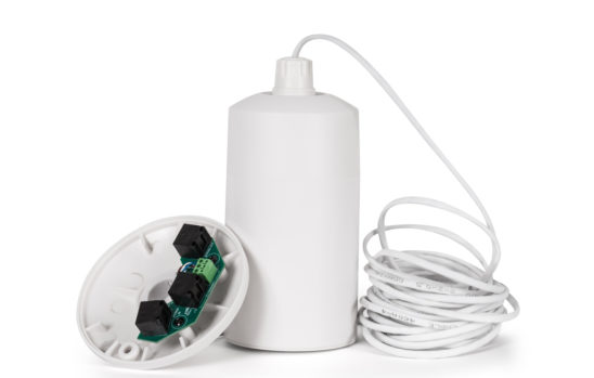
- Ceiling box cover assembly
- Cable assembly
- Cable clamp (2)
- Cable clamp nut (2)
- Pendant mount top and accessory cylinder
Component description
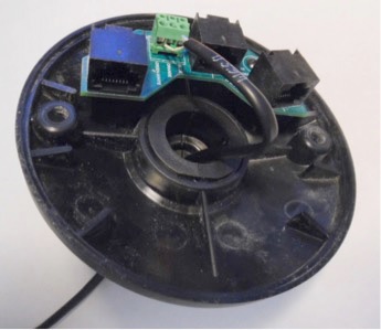
The ceiling box cover attaches to a 4” octagonal ceiling box and includes a connector PCB for all connections. The cover design matches the pendant mount and includes an opening for the assembled cable clamp, nut, and cable.
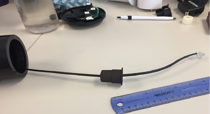
The cable clamp folds around the cable and secures with the cable clamp nut. There are two clamps, one at each end of the cable. The pendant top end is pre-assembled.
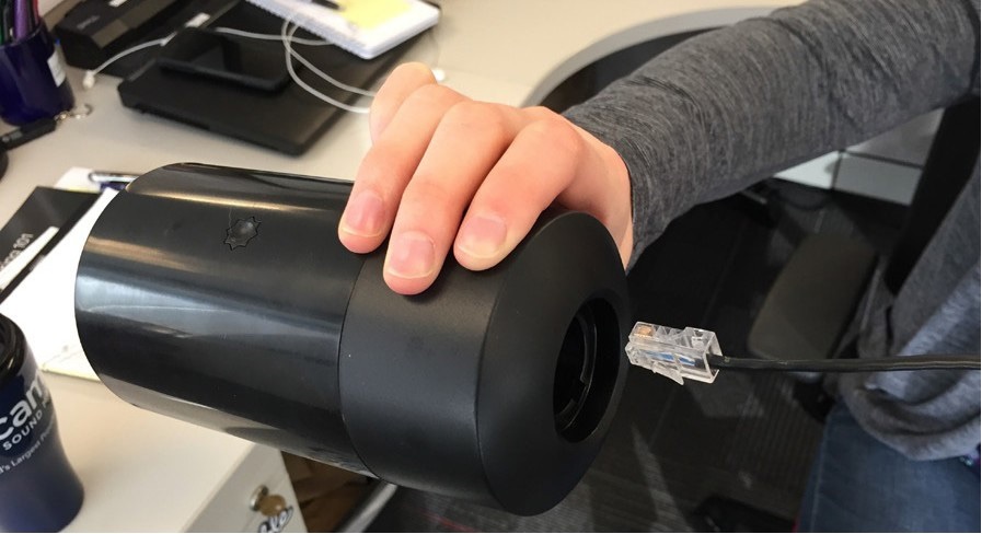
The pendant mount top mates to the cylinder to form the body of the mount. Two fingers on each side snap into the star-shaped holes in the cylinder to hold it in place. The emitter screws into the cylinder.
The cable clamp is designed to securely hold the cable without damage, while providing a convenient method for cable length adjustment. At the ceiling end of the cable, one clamp snaps into the cover. At the bottom, another clamp snaps into the pendant mount top.
The cable assembly is pre-assembled with a cable clamp and nut that inserts into the pendant mount top.
The pendant mount end has an RJ45 connector and the ceiling box end is not terminated. The included cable is 20 feet (6 meters) long and can be trimmed to length.
Pre-Installation
The standard Qt cabling system is used with the ceiling box cover PCB making the connections. The ceiling box cover uses the included screws to secure the cover. Prior to pendant installation, all cables and ceiling boxes should be installed.
The pendant mount system provides a single cable connection from the pendant emitter to the emitter string run. The ceiling box cover connector PCB provides RJ45 jacks for the string run input and the run output as well as an RJ45 jack and three-terminal screw connector for the included pendant cable. Either can be used. The string input connector is set at a slight angle to allow for easier identification.
Note that the length of the pendant cable should not be included in the maximum cable run length calculation.
Identify the locations for the emitters and install the ceiling boxes. Run the string Ethernet cables between the boxes and secure as necessary. Be sure to test any field-terminated cables prior to installation. Troubleshooting mis-wired cables after installation is extremely difficult.
Conduit connectors can be used with both the cover and pendant top. The connector is used in place of the cable clamp and nuts, and will fit in the opening provided.
Determining the cable length
To determine the required cable length necessary to place the emitters at the desired height above the floor, subtract the height of the ceiling from the desired emitter bottom height. Subtract another 4 inches for the length of the pendant mount minus the cable inside the ceiling box. The ceiling box will require about 3 inches for the distance from the cable clamp to the connector.
When installing multiple pendant mounts, unpack the cables and trim one to length as a prototype. Finish and install one mount to test the length. After the length is confirmed, the remaining cables can be trimmed.
Trim the cable jacket back 1 inch. The blue/white wire is not used and can be trimmed off. Strip the remaining wires by 1/4 inch.
Connecting the wires
Insert the stripped wires into the three-terminal plug. Make sure to use the correct color wire in the sockets as indicated on the PCB. The three-terminal plug can be removed from the board to make the connection to the cable easier.
If using an RJ45 connector, assemble using the following connections:
- Pin 3 to Green/White
- Pin 4 to Green
- Pin 5 to Blue/White
- Pin 6 to Blue
Please note that the pinout for the pendant mount cable is NOT the same as emitter cabling. Emitter cabling uses 8 conductors.
The pendant mount cable only uses 4 conductors as described above. A schematic of the pendant mount cable pinout can be downloaded here.
Cover assembly
Slide the end of the cable with the RJ45 connector through the pendant mount top and cylinder assembly (see Figure 1).
Figure 1 - Cover assembly
Attach clamp and nut to cable, leaving about 6 to 7 inches between the clamp/nut assembly and the RJ45 connector (see Figure 2).
Figure 2 - Cover assembly
Pass the remainder of the cable through the top and pull the clamp up into the pendant top. Align the slot in the top opening with the hinge on the clamp. Pull it into the top until it clicks. Then pass the three-terminal plug through the ceiling box cover so the PCB is away from the pendant mount (see Figure 3).
Slide the nut over the three-terminal plug onto the cable with the smaller end towards the ceiling box cover. Wrap the cable clamp around the cable with the threads toward the nut. Slide the nut onto the cable clamp and screw it on loosely. Slide the cable clamp and nut to the correct position on the cable and tighten the nut snugly. Check that the cable is held tightly and doesn’t easily slide through the clamp.
Figure 3 - Cover assembly

Align the clamp into the cover and pull it through until it clicks into place. Plug the cable into the “TO PENDANT” jack on the PCB (see Figure 4) if you are using an RJ45 connection. If you’re using the three terminal connector reattach it to the board.
Figure 4 - Complete cover assembly
Final Installation
Plug the RJ45 connector into the emitter and then slide the emitter into the cylinder. Turn it 90 degrees to lock it in place. Once the emitter is in the cylinder, the pendant mount top cannot be removed.
At the ceiling box, plug the string run cable from the controller into the “IN” jack on the cover PCB. Plug the cable to the next emitter into the “To Pendant” jack. Plug the cable to the remainder of the string into the “OUT” jack.
Dress the cables into the ceiling box and use the included screws to secure the cover to the box.