LVH-900AP (Active Plus, Dual Cabinet) ALC configuration
This article provides step-by-step instructions for configuring Biamp's Community ALC (Amplified Loudspeaker Controller) for operation with the LVH-900AP series of Beamforming Venue Horns.
Overview
The LVH-900AP "Active Plus" models require 11 amplifier channels.
Two ALC1604D 4-channel amplifiers need to be configured as bridged mono for the four LF sections. One ALC404D is used in 4-channel mode to drive the three mid-frequency sections and one ALC404D is used to drive the four high-frequency sections in the cabinets. A total of 11 speaker level pairs drive the dual cabinet array.
All band pass filters, voicing / beamforming FIR filters, and limiters are included in the ALC presets. FIRmaker settings (if applicable) are applied to the Array Group which contains all cabinets in an array. Equalization must only be applied to the Array Group to maintain the intended beamforming.
Each ALC must have its input matrix configured after loading the presets. It is highly recommended to use the same Dante or Analog input to drive each ALC, per speaker cabinet, for ease of integration and to maintain the beamforming performance.
Powersoft ArmoníaPlus 2.0 software is required for programming. Always download the latest speaker preset files from the A+ Marketplace to ensure you have the most up to date loudspeaker library.
Ensure all ALC's have the most up to date firmware before proceeding.
ALC configuration
|
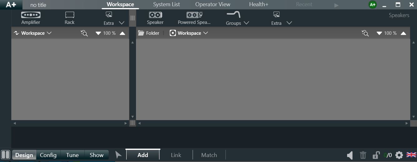
1. Open ArmoniaPlus, Select "New project For Live Sound Project" 2. Select the "design" and "Add" button at the bottom of the screen |
 |
|
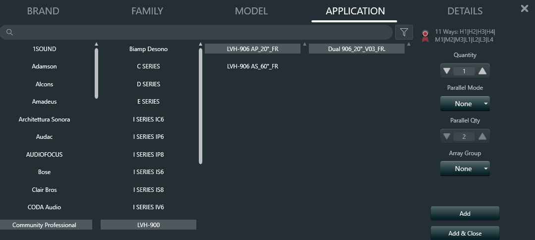
3. Select the "speaker" button at the top of the screen and select the desired LVH-900 speaker file to add.
|
 |
| 4. The speakers will appear in the workspace as shown. | 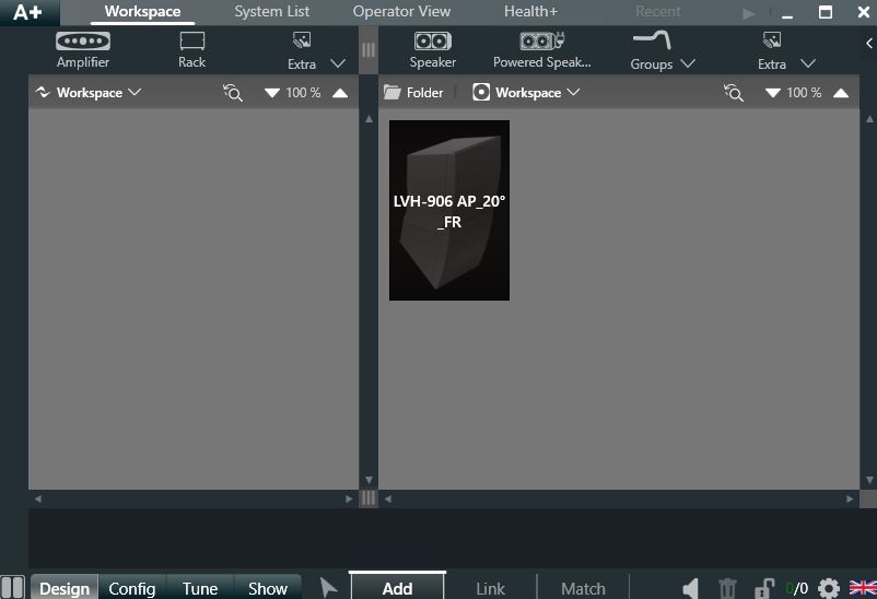 |
| 5. "Add" (2) ALC1604D's from the "Amplifier" tab at the top of the screen. |  |
| 6. "Add" (2) ALC404D's from the "Amplifier" tab at the top of the screen. | 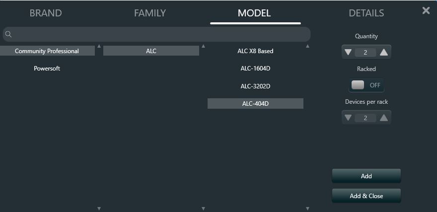 |
| 7. Your screen should look like this. If you make a mistake, you may highlight an object and use the "Trash can" icon in the lower right corner of the screen to delete an item. |  |
|
8. To switch the ALC1604D amplifier to Bridge mode, activate the "Link" button at the bottom of the screen. 9. Left click on the ALC's to highlight channel 1+2, 3+4 and the same on the 2nd 1604D. 10. The "Bridge" indicator highlights at the top of the screen, click it to bridge the channels. |
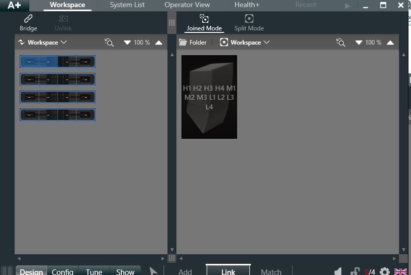 |
| 11. When bridged, a single white dash appears on the face of those (4) channels | 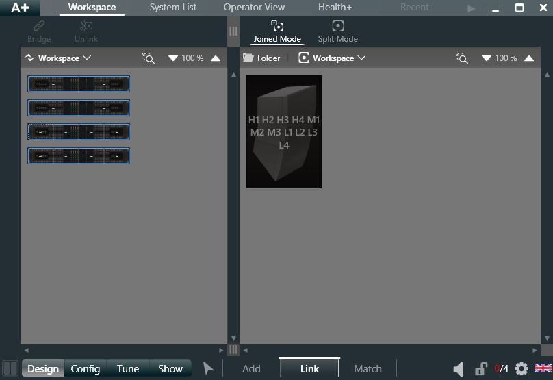 |
|
12. To place the amplifiers in a rack (for ease of organization), select the "Add" button at the bottom of the screen again. 13. Select "Rack" next to the Amplifier tab. Click on the default description above it and label as desired. |
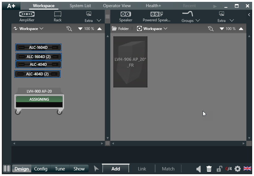 |
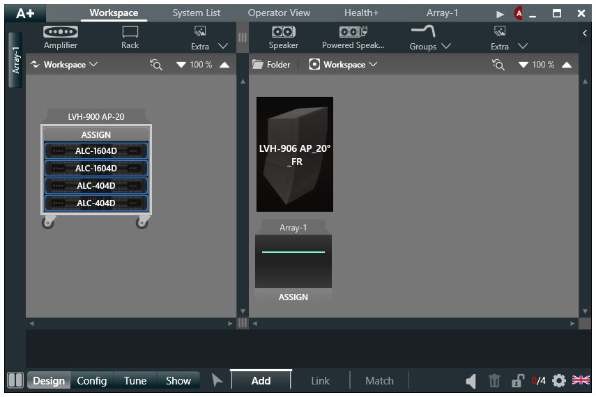
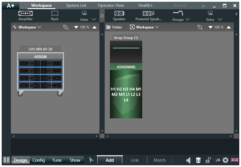
| 14. To load the amplifiers into the rack, click the "Assign" button on the rack and click on each amplifier. | |
|
15. "Add" an "Array Group" from the groups dropdown above the speaker images. To assign the "Array Group" to the speaker for system equalization, click the "Assign" button on it then click the speaker. |
 |
|
16. Once the Advance Group is assigned to the speaker will look like this. The "Adv Group" acts the the system equalizer across all channel inputs. We never equalize individual amplifier channels in a LVH-900 system. |
 |
|
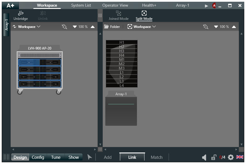
17. To link the speaker to amplifiers, select "Link" at the bottom of the screen. 18. Select "Split Mode" above the speaker. The speaker will show horizontal lines thru it denoting the (11) driver sections.
|
 |
|
19. Work top to bottom. 20. Click on ALC404D channel 1. The speaker input side will automatically index to the next input, click ALC404D channel 2. 22. Continue the process for Mids and Lows taking care to properly assign all links.
|
 |
| 23. Once all speaker inputs are linked to amplifier outputs as shown here, the band passes, limiting and Beamforming settings are loaded into the amplifier channels. | 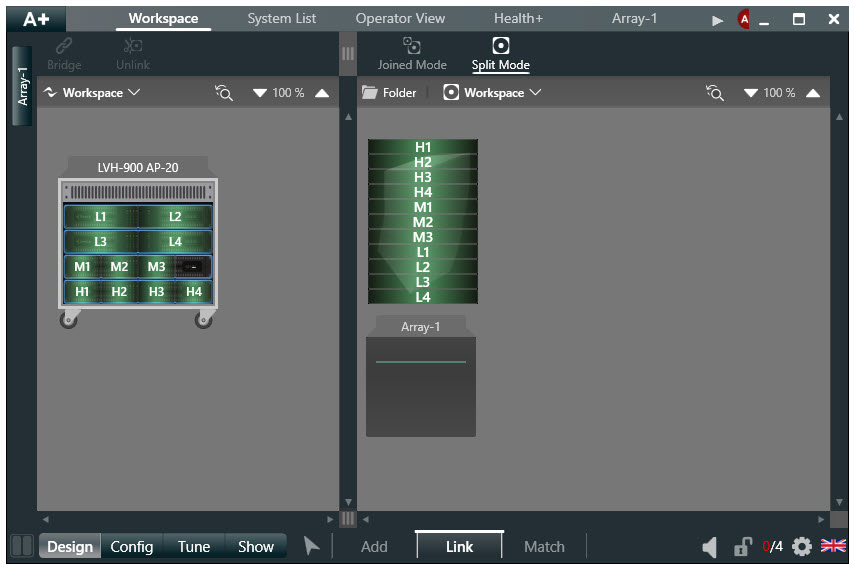 |
| 24. When the "Add" button is activated, we may click on any label and edit it's description in the text box at the bottom of the screen. |  |
|
25. The amplifier outputs are intentionally muted in the Beamforming presets. 26. Once synchronized to physical amplifiers, you may select the "Tune" tab in the lower left of the screen and "Mute" function. 27. When you click on the speaker image, 11 mute buttons will be shown at the bottom of the screen and available for use.
|
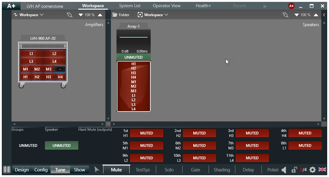 |
| 28. You may also select amplifiers to un-mute individual channels. |  |
| 29. ArmoniaPlus has a handy pink noise generator for initial testing if you select the "TestSys" tab at the bottom of the screen in "Tune" mode. | 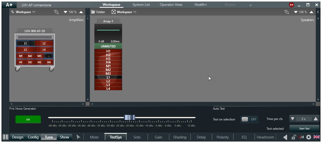 |
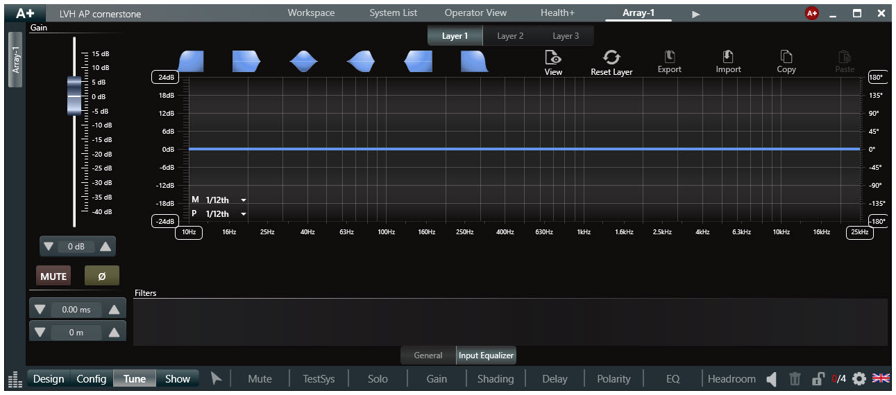
| 30. When you select the "EQ" tab at the bottom, far right of the "Tune" screen you will be brought to the "Input" EQ for the system. Double click on the "Array Group" in the workspace to EQ all speakers in the array. You may also EQ a single speaker by clicking on it and selection "Edit EQ" on the bottom center of the screen.
Beamforming presets include a high-pass filter not shown on this screen. |
 |
| 31. A number of filter types may be selected from the top of the screen and dropped onto the graph. There are highly sophisticated and flexible equalization functions which you may want to read up on. | 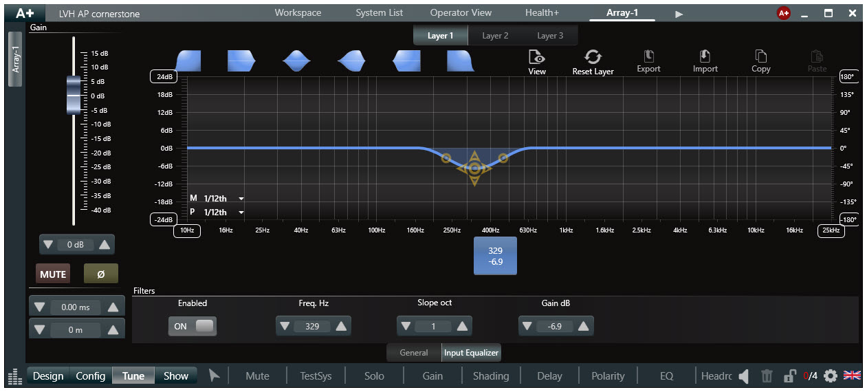 |
| 32. The system EQ curve will be displayed on the "Array group" graphically. | 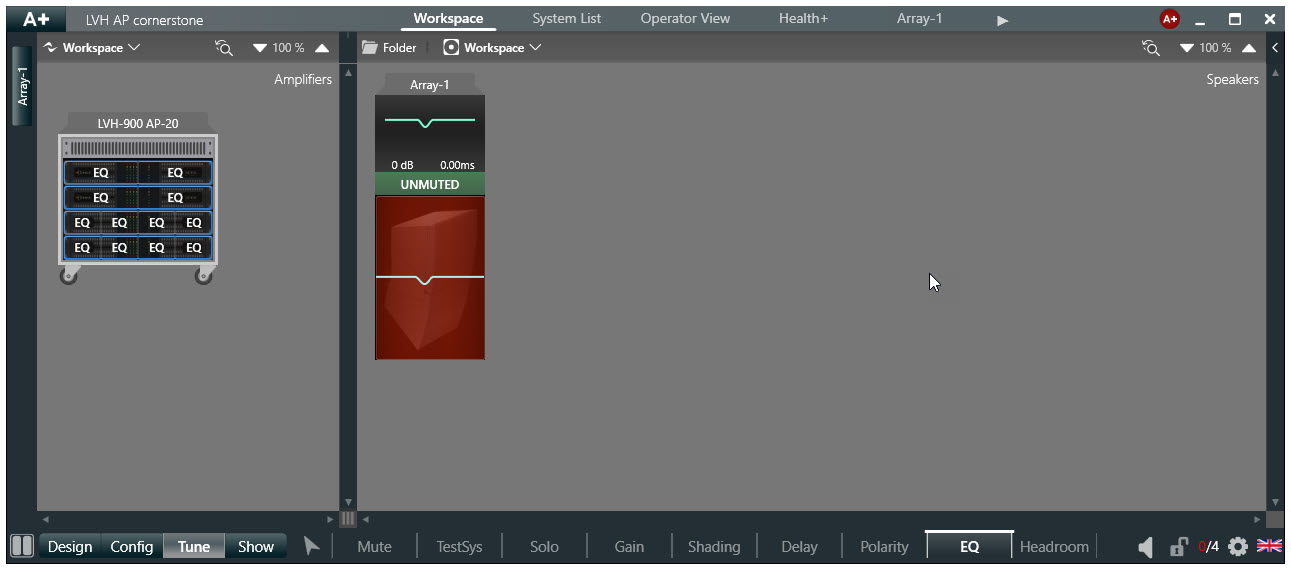 |
| 33. We may configure the input signal source by selecting the "Config" button and the "Input" button on a per amplifier channel basis. | 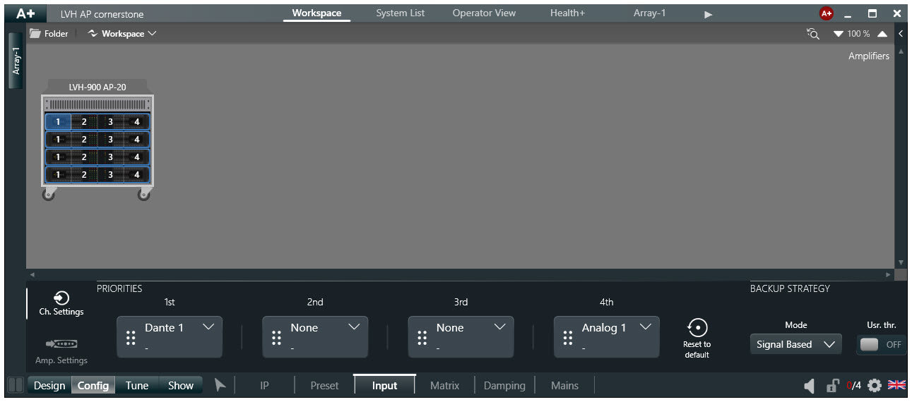 |
|
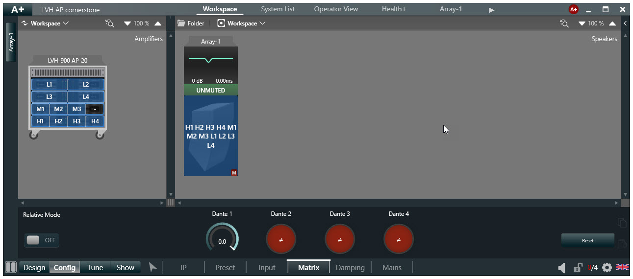
34. To configure the input matrix of racked amplifiers, select "Config" and "Matrix" at the bottom of the screen and select the input routing. Select the same input for all 3 cabinet sections. 35. Adjust your input matrix as appropriate for your application. Double clicking on an input it will turn it up to "0 dB". You may manually adjust the matrix level also. |
 |
| 36. A wide range of diagnostic functions may be shown by selecting the "Show" tab at the bottom of the screen. | 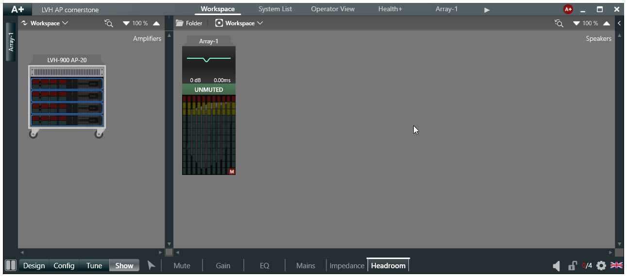 |
| 37. A more condensed overview of amplifier functions and monitoring may be found by selecting "System List at the top of the screen. | 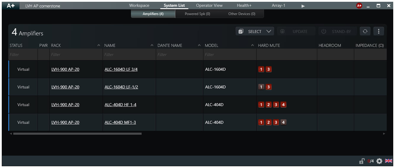 |