Gain structure: input and output levels
This article describes input and output gain structure of audio devices.
Audio components are typically rated by their input sensitivity and/or maximum output voltage. This article explains how to match the output voltage of an audio device to the input voltage range of the next device in the signal chain, and how to adjust input sensitivity to accommodate a variety of voltages from different source devices.
dB, dBu, dBV, dBFS, and dB-SPL
As a basis for the discussion it is important to understand the meaning of and differences between some of the common decibel units: dB, dBu, dBV, dBFS, and dB-SPL. Some background is provided as a prelude to the article.
A decibel (dB) is a logarithmic ratio of two values. A decibel is a "dimensionless" value, meaning that it is just a number, not a unit. While decibels are most commonly associated with audio signals, they don't necessarily have to be. When they are being used to describe audio signal levels, they are often used to compare the amplitude of two audio signals. If those two signals are the same amplitude, then they are said to be 0dB apart. If one signal is twice the amplitude of another signal, then it is 6dB higher. If someone tells you to "turn the signal down by 6dB", then they are asking you to reduce the amplitude of that signal by half.
Decibels are useful because humans perceive sound levels logarithmically. The logarithmic scale is not linear. If you turn up the amplitude of a signal by 6dB, it will be twice the original amplitude. If you turn it up another 6dB, it will be at four times the original amplitude. Another 6dB would put it at eight times the original amplitude. The numbers grow very quickly: if you turn up a signal by 60dB, its amplitude will be 1000 times the original amplitude!
dBu and dBV are decibel units specifically for measuring voltage. Unlike the dB, they are actually units because they can be converted to an actual voltage value. dBu is dB relative to 0.775 volts; such that 0dBu = 0.775 volts. dBV is dB relative to 1.0 volt; such that 0dBV = 1.0 volt. To quickly convert between dBu and dBV note that dBu is always equal to dBV plus 2.21. The V in dBV is capitalized to provide clarity between V and u when writing it down.
dB-SPL is a measure of sound pressure level in the atmosphere, and is used to measure the amplitude of sounds (audio pressure waves) traveling through the air. 0dB-SPL corresponds to a sound pressure level that is barely audible to the average human. dB-SPL is also a unit, because it can be converted to other units of pressure, like pascals.
dBFS, or decibels relative to Full Scale, is used to measure digital audio signal levels. dBFS is another dimensionless quantity, because it is just a number and cannot be converted to another unit. In a digital audio system, 0dBFS refers to the maximum signal level possible, also known as the clipping point. Therefore, dBFS values are always less than or equal to zero. -10dBFS corresponds to a signal that is 10dB lower than the clipping point of the system.
Full Scale
0dBFS (Full Scale) is the clipping point for a signal in a digital audio product. Rather than measuring from the noise floor up, digital signals are measured (or referenced) from the clipping point, or full scale, down. A 0dBFS (Full Scale) signal contains the maximum amount of digital information that can be used to represent the signal being defined.
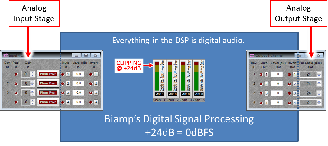
In any digital processor, an output driven with a 0dBFS signal should supply the full output potential of the device, anything beyond that level would be clipping the output. Biamp's digital clipping point at +28dBu (peak). Thus +28dBu = 0dBFS on a Biamp meter. This may not hold true on other manufacturers' devices, if they have designed their products around a different clipping point.
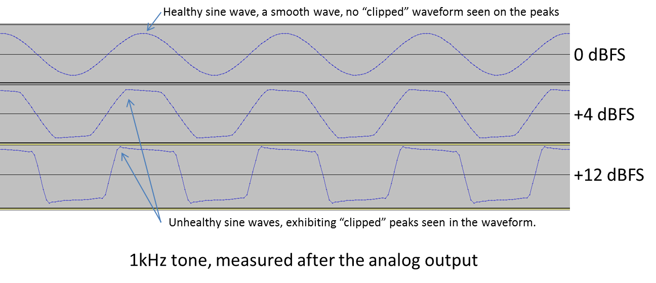
Headroom is an important concept in audio systems - to maintain proper headroom you need to have enough available signal range remaining above the RMS signal to accommodate peaks without clipping. Clipping is a deformation of the audio waveform as a result of saturating or overdriving the system.
An analog system will clip when there is no remaining voltage available to describe the louder signal - it has reached the maximum voltage level the system can reproduce, if it attempts to go louder the loudest parts are "clipped" off. In a digital system clipping occurs when there are no further data bits available to encode the signal - it results in digital noise or hash.
With Biamp floating-point DSP devices, a signal greater than +28dBu peak will clip if it exits the DSP via the analog or digital outputs. Signals that are greater than 0dBFS will clip if they are transmitted across CobraNet, Dante, AVB, or USB digital audio paths.
For live music performances with large dynamic range, sufficient headroom is usually considered to be 18-20dB. The +4dBu "pro audio" average RMS level plus 20dB of usable headroom for peaks necessitates +24dBu before clipping for musical performance, thus the industry has largely adapted to embrace +24dBu as the standard on pro audio devices, at least in North America.
To do the math for dBFS, this would mean your RMS average level should be about -20dBFS, which equals +4dBu (24dBu - 20dB = 4dBu; 0dBFS - 20dB = -20dBFS). This 0dBFS = +24dBu is not a hard and fast rule across all manufacturers, be sure to check your equipment to see what the 0dBFS level is referenced to.
But what about noise floor? A 24-bit digital audio system (such as the Biamp DSP) has 144dB of range, so the operating floor of the sampling depth is still 120dB below a -24dBFS signal. A 16-bit sample has a range of 96dB, leaving 72dB of downward range. In either case, the noise floors presented by the microphones and the environment itself will be your concern, not the range of usable bit depth.
Analog output settings
(Note - to see the controls mentioned here in Audia or Nexia software, be sure to enable Output Attenuation when creating the Output block.)
At Biamp, we reference our meters so 0dB = 0dBu = 0.775 volts when operating at the +24dBu (default) output setting. If a lower Full Scale (dBu) output setting is selected the output voltage is scaled appropriately.
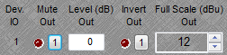
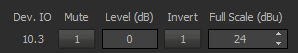
The Biamp analog output stage has selectable fixed settings of -31dBu, 0dBu, 6dBu, 12dBu, 18dBu, or 24dBu. This is a maximum voltage value produced when the analog output is driven to the onset of clipping.
Recall that Biamp shows its clipping point as +24dBu on its meters. A +24dBu (0dBFS) signal will drive the analog output to its maximum voltage. The full scale digital signal is converted to an analog signal at the output block, the dBu setting allows you to specify the maximum analog voltage delivered by the output.
Changing the Full Scale Out setting will vary the voltage being supplied at the analog output connection. It is important to look at the spec for the next device in the signal chain to ensure that the voltage being supplied does not exceed its input sensitivity rating.
Within the output block, Level (dB) Out allows you to fine tune the output level before the conversion to an analog signal. It modifies the level while it is still in the digital domain. Its functionally the same as a Level control placed in line before the output block.
The -31dBu setting provides a mic level signal from the output.
| Analog output block settings | Analog output maximum voltage (Vrms) |
| Full Scale (dBu) Out = 24 dBu | 12.282 Vrms |
| Full Scale (dBu) Out = 18 | 6.156 Vrms |
| Full Scale (dBu) Out = 12 | 3.085 Vrms |
| Full Scale (dBu) Out = 6 | 1.546 Vrms |
| Full Scale (dBu) Out = 0 | 0.775 Vrms |
| Full Scale (dBu) Out = -31 | 0.0218 Vrms (21.8 mVrms) |
You have probably heard the terms "pro" level and "consumer" level. Pro level is +4dBu = 1.228V RMS and is typically seen in devices with balanced connections. Consumer level is -10dBV = 0.316V RMS and is typically seen in devices with unbalanced connections. The "level" is an average RMS level for program material at unity gain point within the device. Peak levels can be 20dB or more above the average RMS level.
"Consumer" level of -10dBV equals -7.7825dBu, so it is 11.7825dBu (about 12dBu) less than "pro" level. Note it is not a "14dB" difference, since two different scales are being referenced (dBV and dBu) you need to convert one of the values to the same scale as the other and then look at the difference in level between the two.
VU meters are the ballistic pointer type meter seen on most older analog gear. On professional (studio grade) equipment 0VU = +4dBu. This is why we refer to +4dB as "pro level", it is a legacy term from the old days of doing sound and referencing 0 on the VU meters.
At Biamp, we reference our meters so 0dB = 0dBu when operating at the +24dBu (default) output setting.
Analog input sensitivity
The analog input block's Gain In setting allows you to set a value from 0dB to +66dB in 6dB increments. This setting is used to match the input sensitivity of the device to the connected source. As you raise the Gain In value, you are amplifying the incoming voltage supplied by an external device. A microphone has a very, very low output voltage relative to a CD player's line out or a mixing console's line out so you would use a higher Gain In value for a mic (amplifying it, or "gaining it up", more), and lower for the line level devices (which need less gain increase).
The goal is to bring the voltage up to an average of 0dBu, the nominal operating voltage of the Biamp hardware. This will optimize the incoming voltage level for the D-A conversion hardware - assuring the best signal-to-noise and headroom are maintained.
Note that when you set input gain you are matching voltage levels between devices, not matching impedance. Impedance matching is not necessary or desirable - the manufacturer has already designed the components to play nicely with other components.
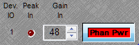
Phan Pwr or Phantom Power is a 48 volt DC current applied to the input circuit to provide power to a condenser / electret microphone or an active Direct Box. It should never be used for devices which do not need phantom power.
When a source device is sending a tone measuring at 0dB on its meters, the input level meters on the receiving device should also read 0dB.
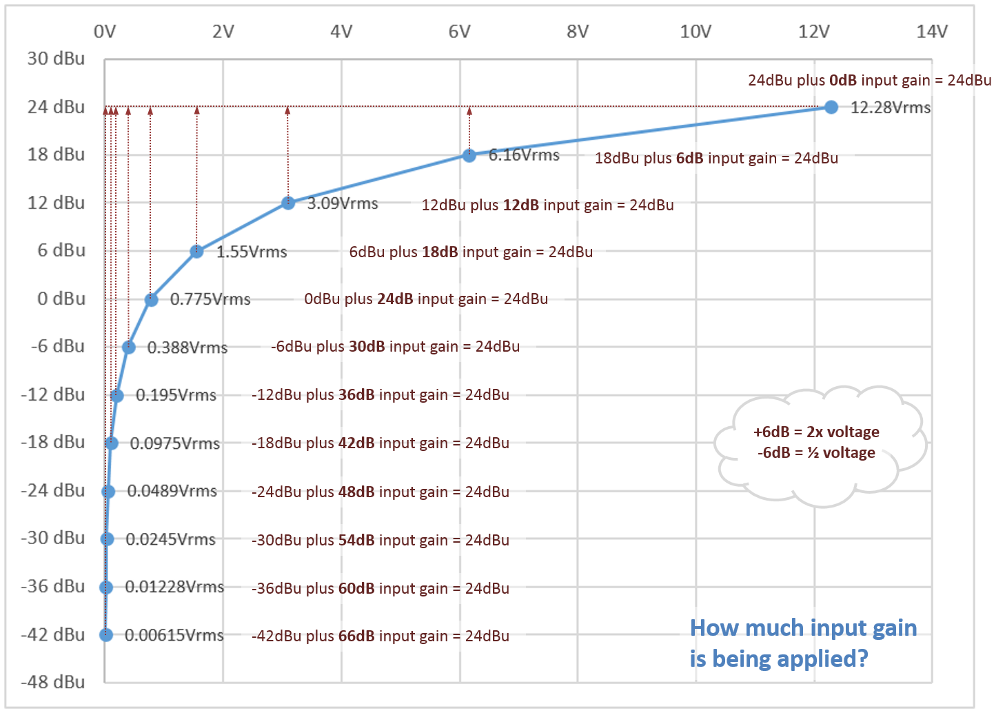
- For a line level device providing +24 dBu (or 12.23 Vrms) maximum output voltage to a Biamp device the correct input gain setting is 0dB. At 0dB an input signal is passed into the Biamp device at unity gain - no gain has been added to or subtracted from the signal.
- For a line level device providing +12 dBu (or 3.065 Vrms) maximum output voltage to a Biamp device the correct input gain setting is 12 dB. Since the supplied voltage is decreased you need to increase the input sensitivity.
- For a mic level device providing -31 dBu (or 0.021Vrms) maximum output voltage to a Biamp device the correct input gain setting is +54 dB with a "fine tuning" of +1 dB to match the level of the input. Again, since the supplied voltage has been decreased you need to increase the input sensitivity to get back to 0dB.
See the chart below; and note that 0dB Gain In is not the same thing as 0dBu of voltage.
The Biamp DSP can handle a maximum input voltage of +24dBu. A Gain In setting of 0dB means that for a signal that is coming in from a device which also produces a +24dBu maximum level no correction offset is being applied to match the gain structures. For any device providing an input voltage whose (potential) maximum level is lower than +24dBu we need to provide an offsetting make-up gain to bring the clipping points of the two devices into alignment. This applies to any input device, whether it is a microphone, a PC, a codec, a music server, a mixing console, or another DSP unit. Similarly, if the device has a maximum output level greater than +24dBu then that device needs to be attenuated to limit its maximum level to +24dBu.
The Gain In setting is used to match voltages between devices by boosting a lower voltage analog input signal up to an average of 0dBu RMS as it enters the DSP unit, just before the A-D (analog to digital) conversion.
| "Gain In" Setting (aka - sensitivity) | Input source type | dBu (maximum level from the source) | Vrms (maximum level from the source) |
| 0dB | line level | 24 dBu | 12.28 Vrms |
| 6dB | line level | 18 dBu | 6.16 Vrms |
| 12dB | line level | 12 dBu | 3.09 Vrms |
| 18dB | line level | 6 dBu | 1.55 Vrms |
| 24dB | line level | 0 dBu | 0.775 Vrms |
| 30dB | line level | -6 dBu | 0.388 Vrms |
| 36dB | mic level | -12 dBu | 0.195 Vrms |
| 42dB | mic level | -18 dBu | 0.0975 Vrms (97.5 mVrms) |
| 48dB | mic level | -24 dBu | 0.0489 Vrms (48.9 mVrms) |
| 54dB | mic level | -30 dBu | 0.0245 Vrms (24.5 mVrms) |
| 60dB | mic level | -36 dBu | 0.01228 Vrms (12.28 mVrms) |
| 66dB | mic level | -42 dBu | 0.006156 Vrms (6.156 mVrms) |
Test it
You can measure the peak Vrms output value of the device by connecting a multimeter across pins 2 and 3 (+/-) of a line output.
Testing the maximum output voltage
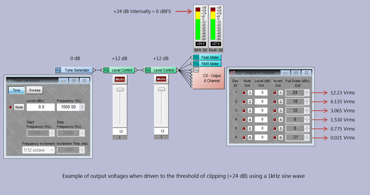
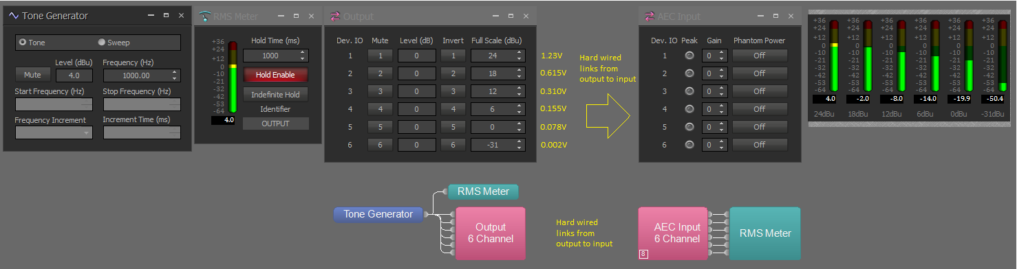
Use a tone generator set to a 1kHz tone at +24dBu, this can be wired directly to the output in your layout.
Sine waves have a crest factor of +3dB. If you attach both a peak meter and an RMS meter to the signal path you will see that the RMS meter reports +24dB and the peak meter reports +27dB
Recall with dB that a drop of 6db (-6dB) equals 1/2 the voltage. Adding 6dB equals a doubling of the voltage.
| Source = 1kHz @ +24dBu |
Full Scale (dBu) Out = 24 |
12.28Vrms |
| Source = 1kHz @ +24dBu |
Full Scale (dBu) Out = 18 |
6.16Vrms |
| Source = 1kHz @ +24dBu |
Full Scale (dBu) Out = 12 |
3.09Vrms |
| Source = 1kHz @ +24dBu |
Full Scale (dBu) Out = 6 |
1.55Vrms |
| Source = 1kHz @ +24dBu |
Full Scale (dBu) Out = 0 |
0.775Vrms |
| Source = 1kHz @ +24dBu |
Full Scale (dBu) Out = -31 |
21.8mVrms |
Note: All measurements are made with internal RMS meters reading +24, fed with a 1KHz sine tone. Expect a small margin of error on your voltage readings since there are tolerance variations in all of the components involved. Differences greater than a few percent should be cause for further investigation.
Testing with a +4dBu tone.
A 1kHz tone at 4dB RMS in the Tesira system will measure roughly 1.23V RMS at the 24dBu output setting, 0.615V RMS at the 18dBu output setting, 0.310V RMS at the 12dBu output setting, 0.155V RMS at the 6dBu output setting, 0.078V RMS at the 0dBu output setting, and 0.002V RMS at the -31dBu (mic level) output setting.
A 1kHz tone at 0dB RMS in the Tesira system will measure roughly 0.775V RMS at the 24dBu setting, 0.388V RMS at the 18dBu setting, 0.195V RMS at the 12dBu setting, 0.097V RMS at the 6dBu setting, 0.048V RMS at the 0dBu setting, and 0.001V RMS at the -31dBu setting.
Practical example - output
We know that the Biamp DSP has a maximum output voltage of +24dBu. Due to differences between products it is possible that this level will be too high for the input of another device, causing distortion as the input is overloaded. Here are some examples of mismatches.
Example 1:
When we connect it to an amplifier we need to know the specifications for that amp. Here is a sample from a professional quality amplifier's data sheet:
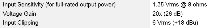
Notice the input clipping occurs at +18dBu. If we use the full +24dBu potential output of the Biamp we will be clipping the amplifier on a regular basis, causing the system to sound bad and probably damaging or destroying speakers.
It is necessary to match the output voltage of the Biamp DSP to the input voltage of the amplifier. Changing the Biamp DSP's output setting to +18dBu limits the maximum voltage it will supply when operating at full volume to a level appropriate to the amplifier's input circuit.
The importance of this calibration becomes clear when we consider setting limiters for an amplifier to protect our speakers. If the amplifier is rated for a +18dBu maximum input signal and the DSP sends a +24dBu signal to it the amplifier will see twice the allowable input voltage and will be clipping. If you have set up your system limiting in the DSP it is possible to be below the limiting threshold level and still be clipping the amplifier inputs and damaging the attached speakers. It is vitally important to understand the relationship between the components and recognize that there is not a "standard" for all manufacturers.
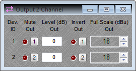
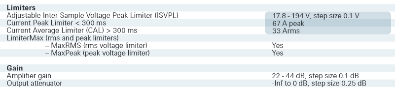
Example 2:
 Here is another example where the maximum input voltage allowed by an amplifier is well below the maximum that the Biamp DSP can provide. In this case a Full Scale (dBu) Out setting of 0dBu (zero dBu) would be the correct one to specify. It will allow a maximum of 775mV to be produced by the DSP at maximum level. Now the amplifier's attenuation pots (volume knobs) can be adjusted for the room without fear of the input signal clipping.
Excellent Resource:
Digital input settings - amplifiers
When an amplifier receives its input signal via AVB, CobraNet, or Dante the signal will come in referenced to 0dB Full Scale (0dBFS).
As with analog amplifiers, most digital amplifiers will provide an attenuation control, allowing you to reduce the signal level being fed into the amplifier - either via a front panel interface or software interface. This is a line level control, located post-input, before the amplifier stage. The attenuation controls will have a range of minus infinity to 0dB.
The amplifier may also have an amplifier gain setting. Changing amp gain can be seen as changing the amplifier’s sensitivity, you are adjusting the input level that is required to provide maximum rated output power to the connected load. Higher amplifier gain equals higher input sensitivity, meaning a lower input level is required to reach maximum output power. Amp gain primarily affects the amount of headroom for the system.
Adjusting gain (sensitivity) should be utilized to optimize the ratio of amplifier headroom to noise floor. At higher gain settings (higher sensitivity), more of the noise floor will be amplified and the available headroom before clipping will be lower.
In configuring an amp for the digital input, refer to its manual to find the optimal setting for your amplifier. In the example shown above, further reading of the manual reveals that for a Dante digital input the amplifier's attenuation level should be 0dB and the amp gain setting should be 35dB.
Digital output settings - Audia EXPO
The Biamp EXPO, EXPO-4, and EXPI/O-2 are standalone CobraNet devices that can receive digital audio from a transmitting CobraNet device.
EXPO
Output level adjustments on the EXPO (8-channel, single full rack space) are made via analog attenuation pots on the front panel of the device. A small flathead screwdriver is the tool required. Fully clockwise will give +24dBu output, rotating the screw fully counterclockwise will reduce the output voltage to -31dBu (mic level). It is a variable output, there are no detente positions between the two limits. To calibrate the analog output of the EXPO to the input of the next device send a 1kHz sine tone at 0dB RMS over CobraNet to the EXPO. Set the next device to its lowest input sensitivity, normally 0dB or line level on the input (and ensure phantom power is disabled), then connect the EXPO output to the input of the next device. Observe the input meter of the device: if the meter is above 0dB use the attenuation pot on the EXPO to reduce the signal to 0dB on the input meter of the new device; if the meter is below 0dB increase the input sensitivity of the new device to raise the input signal to 0dB.
EXPO-4 and EXPI/O-2
Analog output level adjustments on the 1/2 rack space EXPO-4 or EXPI/O-2 are made via the front panel menu under OUTPUT GAIN.
Since it is a digital device (CobraNet) the output is referenced from Full Scale Digital (FSD) or dB Full Scale (dBFS). Recall that 0dBFS is the maximum possible setting, anything higher would be into digital clipping.
The available settings are 0dB, -6dB, -12dB, -18dB, -24dB and -55dB. These are all dBFS values.
These equate to +24dBu, +18dBu, +12dBu, +6dBu, 0dBu, and -31dBu in the Audia output block. These are all dBu values.
There is a 24dB offset due to the different scales being used. The analog output voltages of the EXPO remain consistent with what the Audia output block provides.
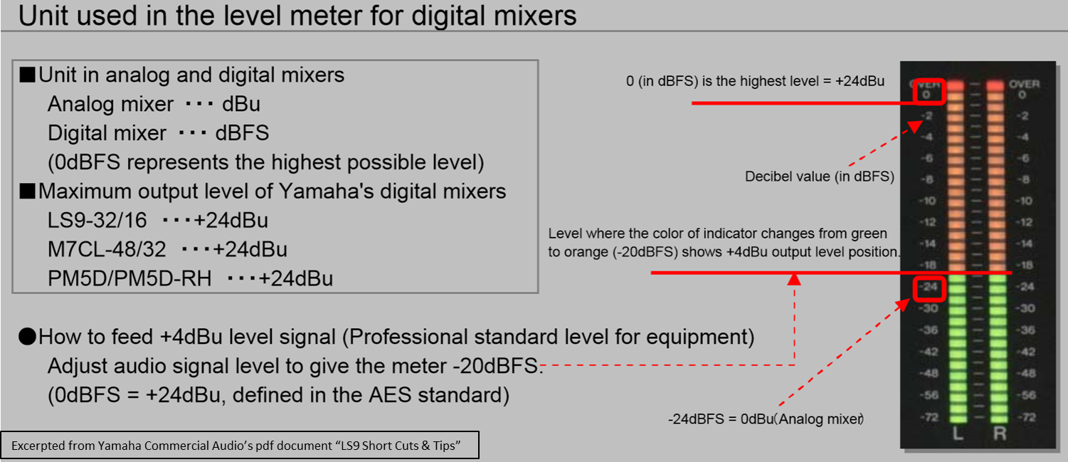
Calibrating meter levels to a Yamaha LS9 console
Yamaha digital consoles reference their Full Scale meters to 0dBFS = +24dBu. The correct average level to maintain safe operating headroom should be at about -20dBFS to -24dBFS. The LED colors change from green to orange at -20dBFS (+4dBu) to provide a visual indication of your level.
The Yamaha LS9 can connect to Tesira via analog connections or digital audio networks (AVB, CobraNet, or Dante)
When connected to the Biamp Tesira a signal registering -24dB on the Yamaha's output meters will register as 0dB on the Biamp's input meters.
The meter's reference point is different in each product. The actual level with respect to the digital clipping point of both products is the same.
A 0dB output from the Biamp Tesira to a Yamaha console will be seen as -24dBFS at the input. This is the correct level. It shows that there is 24dB of headroom remaining before the digital signal clips.