VTC with Cisco TelePresence Codecs
This article describes the basic physical connections required for interfacing with a Cisco TelePresence product. This article also includes disabling the AEC (Acoustic Echo Cancellation) or Echo Control and Loopback features in the Cisco codec.
This is not meant to be an exhaustive product guide to the C40; some settings and interface screenshots in the Cisco software may change as their user interface is updated. Some settings are similar in the C60, C90, and other Cisco products.
The SX10 and SX20 are reported to be recommended for use as standalone products and not used as an integration product. The SX80 is a common source of frustration as settings are made via CLI (command line interface). Please contact Cisco for support if needed. Verify that the far end is handling echo cancellation for you. If they are routing your audio back through their codec you will hear an echo which will stop when you mute the input from the SX80.
C-40 Physical connections
Biamp to Cisco
An output on the Biamp device will be connected to the C40's Mic/Line In (balanced XLR) connection. This will carry the audio being transmitted (VTC Tx) to the VTC far end.
- The Cisco's Input type should be set to Line.
- Phantom power must be turned off for the C40 Mic/Line Input (defaults to off in Line mode)
- The Cisco's input level should be set to 0 (defaults to 0 in Line mode)
Cisco to Biamp
The C40's Line Out (unbalanced RCA) connection will connect to an input of the Biamp device. This input will be the audio received (VTC Rx) from the far end which will play out in the room.
- AEC, if available, must be disabled for this input channel on the Biamp (AEC is only for microphones).
- Phantom power must be disabled for this input channel on the Biamp.
- In the Cisco device, ensure that the Audio > General > SelectedOutputConnector is set to Speakers.

See the Cisco C40 physical interface guide document for further detail.
SX-80 physical connections
Input
- Adjust the source device output connected to the SX-80 mic input to be mic level (-31dBu on the Tesira output block), or,
- Adjust the SX-80 input gain to -2dBu to allow the line level source to align properly (+24dBu on the Tesira output block).
 Connections 1-8 are mic-line inputs (1-8) and connections 9-12 are line inputs (1-4). VU meters are available via the Cisco web interface in Setup > Peripherals : VU-meters.
Inputs 1-8 offer a mic pre-amp which must be adjusted to accept a line level source - simply setting it to "Line" in the software does not affect the sensitivity but does disable phantom power.
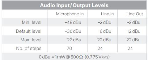 The SX-80 codec's full scale level is 22dBu, Biamp's default is 24dBu.
Setting the Cisco's input level (any input) to -2dBu should put them in sync with Biamp's default line level output.
Be sure to disable phantom power on the Cisco mic channels if connecting Biamp processors to them!
Output
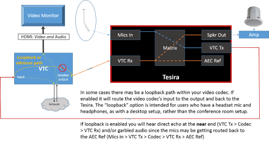
Depending on the configuration of the SX-80 any of the 12 inputs as well as VTC audio may be routed to line outputs 1-4 for local reinforcement or far end transmit. Be sure these are properly configured so that the far end is not looping back internally in the SX-80.
Line outputs 5 and 6 are "record outputs" and will always contain the analog inputs as well as far end and program material. These should not be used for reinforcement or transmit to the far end.
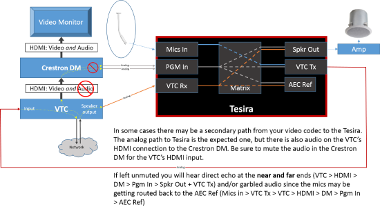
Additionally, the output being sent to the analog outputs may be mirrored on the HDMI outputs and can lead to confusing loopback echo conditions (see Loopback below).
AEC / echo control
AEC can only be provided by one device in a system, in this case we are using the Biamp device. Each of the mics must be connected to an AEC input with AEC enabled.
The C40's Line Out must be connected to a Biamp input with AEC disabled, or to a non-AEC input.
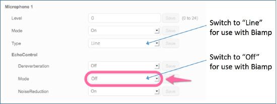
The EchoControl mode (acoustic echo cancellation) must be turned Off within the C40 interface. Please see the Cisco documentation for further details - http://www.cisco.com/c/dam/en/us/td/docs/telepresence/endpoint/codec-c-series/tc6/troubleshooting_guide/tc_troubleshooting_guide_tc60.pdf
Distorted audio
Occasionally we hear reports of a video codec sending distorted audio to the far end. This can be a tricky issue to debug but is typically a gain structure issue.
When Tesira is wired via analog output to the VTC it is critical that the Tesira output gain setting is matched to the input sensitivity of the VTC.
E.g.- the VTC expects mic level input (-31dBu) but Tesira has been left at the default setting of +24dBu. The result will be heavily distorted input on the VTC when the near end talks. It is possible that this clipping can saturate input circuits in VTC devices and cause audible distortion on the VTC's outputs.
The VTC's distorting output is in turn connected to the Tesira inputs and feed both the local speakers and the AEC Reference. The clipped audio being fed into the AEC Reference will then garble and distort the spoken word of the mics as the AEC attempts to strip the distorted audio components from the transmit stream. Over time, as the near end continues to talk, this interaction makes the already overdriven audio sound even more corrupted at the far end.
Verify the input sensitivity setting of the VTC, then verify the analog output gain settings of the Tesira. Adjust as needed to bring them into proper alignment and test again.
Loopback
Within Cisco video codec
Via Crestron DM or video switcher
Mute Synchronization
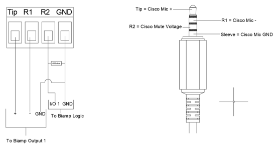
Some Cisco CODECs such as the Room Kits provide voltage outputs between mic and ground pins on TRRS connectors. This voltage is intended to display mute state on the proprietary Cisco microphones but can be used instead to communicate the mute state of Cisco to the Tesira via GPIO. The following image shows the required 400 ohm resistor to yield roughly 8 volts for the un-muted state and 5 volts for the muted state.
Once this voltage information from the Cisco device is available to the Biamp GPIO port, the following block combination can be used to sense the voltage transition and mute accordingly in the Tesira device:
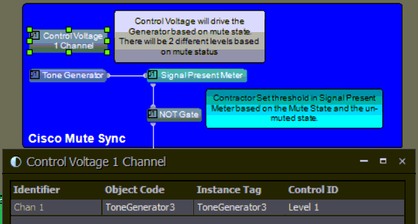
Downloadable Tesira example/primer file.
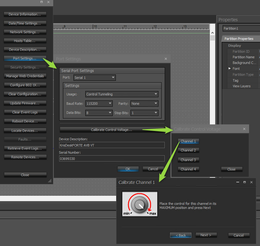
The GPIO Control Voltage is calibrated via Device Maintenance as shown. The Min and Max will correlate with the Mute/Unmute of the CODEC:
