Parlé-series microphones tips and tricks
Biamp's Parlé Series Beamtracking™ Microphones can be used in a wide variety of applications. We've developed some tips and tricks to ensure that the Parlé microphone is always performing at its best and that installations always go smoothly. This article is intended to provide some extended information pertaining to the installation and programming of these microphones.
Parlé Processing Block
To simplify programming of a system containing Parlé microphones, the Parlé Processing Block available in the control blocks section of Tesira Software. The Parlé Processing block supports array counts from one to twelve of the same microphone type.
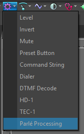

The block contains presets for varying room acoustic conditions or can be adjusted as required for the system. See the Parlé Processing Block article for additional information.
If the AI Noise Reduction block is used with Parle mics in a TesiraFORTE X, then a modified signal flow is recommended to keep dynamic processing post-noise reduction.
Beam Outs and Combiner Blocks
For applications that require using individual beam outs or auto mixer combiners, refer to the Parlé Custom Processing Catalog article. The Parlé Processing Block does not support connection to beam outputs or to a combiner block.
It is possible to use the audio from the individual beams instead of the overall 4-beam mix with the TCM-X, TCM-XA, and TTM-X series microphones. Please refer to the Parlé Beam Outputs and Parlé Custom Processing Catalog articles for additional information.
Mute Control using Tesira Text Protocol (TTP)
There are two ways to control the internal mute of the Parlé Processing Block when using an external control system. Refer to the Tesira command string calculator for the appropriate TTP commands.
One option is to use a logic state to toggle the mute on and off while monitoring the state using a subscription to a logic meter.
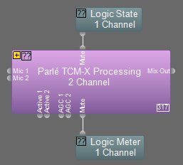
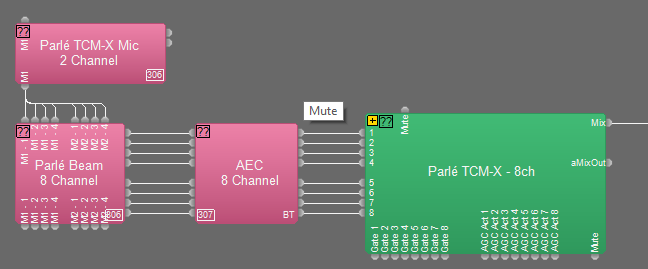
The second method is to directly access the mute control block embedded within the Parlé Processing Block. You will need to know the instance tag just as you would when addressing any other block using TTP. To get the instance tag, set the Parlé Processing Block to the "Custom" preset then click the "+" icon to expand the block. Inside the expanded block, select the mute block with the left mouse button and the instance tag is displayed on the left side of the status bar located at the bottom of the Tesira software window as shown below.

Auto Mixer Gate Hold Time
Some room layouts will benefit from a faster transition between microphone arrays than others. This transition time can be fine-tuned by doing the following:
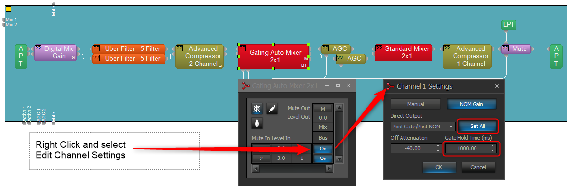
- Use the "Custom" setting of the Parlé Processing Block and expand or expand the Custom Block, then double-click on the Beamtracking Auto Mixer.
- Right-click on one of the blue "On" buttons and select "Edit Channel Settings."
- Make sure the "Set All" button is active (blue).
- Leave the "Off Attenuation" setting at -40, but edit the "Gate Hold Time (ms)" to a lower value. The default value is 1000 ms, but we've observed good results when this value is set between 400 and 600 ms. Please consider the number of microphone arrays and the intended use of the room/system when configuring this setting. If in doubt, contact Biamp Support while commissioning this setting.
Parlé Microphone Array Logic
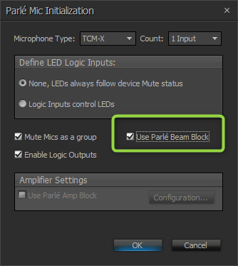
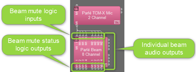
The Parlé input block provides a series of logic nodes in order to customize the muting and LED behavior of the microphone pendant. Logic is enabled from the Parlé Mic Initialization dialog. The following configuration within the Initialization Dialog on the left would produce the input block configuration on the right.
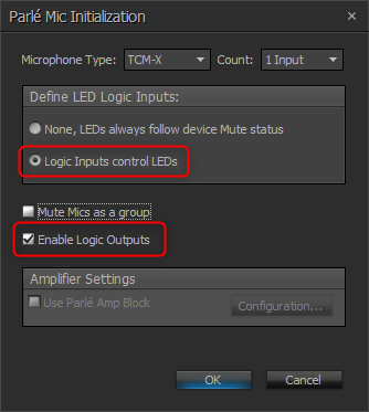
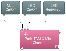 All logic nodes are provided on a per-array basis. The TCM-1 input block can support a maximum of 3 microphone arrays. The TCM-X and TTM-X input blocks each support up to 2 microphone arrays. The exception to this is the "M1" nodes (for mute control and status feedback logic). If selecting "Mute Mics as a group," only a single logic input/output will be added for mute control and this will affect all channels simultaneously.
The "LED1" logic input will drive the LEDs for the corresponding pendant. The LEDs will remain off while receiving a logic low signal (0) and will turn on when they receive a logic high signal (1).
The "RG1" logic input will select the LED color. A logic low signal (0) will set the LED color to red and a logic high signal (1) will set the LED color to green. Please note that the LED will not illuminate until the "LED" Logic input is driven high (1).
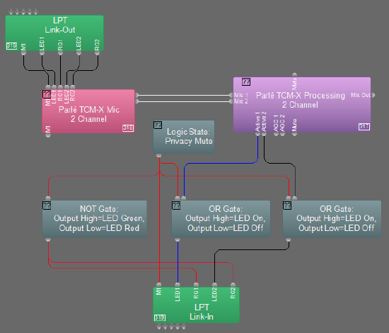
The granularity provided by these controls allows for customized behavior to suit the LED needs for a variety of situations. One example of this is to enable the green LED only when a pendant is active (gated on), while also allowing for a privacy mute that sets all pendants' LEDs to red for the duration of the privacy mute. The diagram below shows how logic could be wired to accommodate this scenario in a dual-array system. This is accomplished by using the Mic Active logic output of the Parlé Custom Block (included in Tesira software versions 3.11 and above) in conjunction with a Logic State serving as the trigger for the privacy mute.
- Logic State - Privacy Mute
- When Logic State output is high, the following conditions are met:
- TCM-X M1 Logic input is set high, muting both pendants.
- OR Gate outputs are set high, activating the LEDs on each pendant.
- NOT Gate output is driven low, setting the LED color to Red.
- When Logic State output is low, the following conditions are met:
- TCM-X M1 input is set low, unmuting both pendants.
- OR Gate outputs are set low, deactivating the LEDs on each pendant.
- NOT Gate output is driven high, which will set the LED color to Green.
- When Logic State output is high, the following conditions are met:
- Mic Active Logic from Custom Block
- When a Mic Active logic output is high and the Logic State is low, the following conditions are met:
- OR Gate output is set high, enabling the LED for the active pendant.
- Since the Logic State is low, the NOT Gate output is driven high, which sets the activated LED color to green.
- When a Mic Active logic output is high and the Logic State is low, the following conditions are met:
Indicate EX-UBT or USB X stream activity using Parle LEDs
The EX-UBT and USB X blocks provide indication of USB streaming activity, mute sync state, and hook switch state with some UC clients, including Teams. Only one UC client should be open at a time on the host PC to ensure one program is not blocking mute sync behavior for another.
On hook and off hook state commands are not implemented on a consistent basis across all UC platforms and web-based UC may not support certain HID states. We recommend monitoring both the streaming and hook states in order to determine which will provide better results for the given application. Note, when available, hook switch should provide more accurate UC call state feedback.
Below are two Tesira Processing Library files that can be imported into Tesira software. Choose whether you are monitoring for USB streaming activity or USB hook state, then drag the desired block into your layout. Wire logic nodes according to the labels on the block. The option for "Logic Inputs control LEDs" must be selected in the Parle mic block properties.
Parle Mic LED States - USB Hook
Parle Mic LED States - USB Streaming
Incorporating these blocks will reflect EX-UBT / USB X streaming or hook status, along with mute status, via the LEDs on the Parle mics.
On the Parle mic block the LED node turns the LED on when the state is high. The RG node switches the mic LEDs green when input is high, red when low. (A USB mute (M) logic output connected via a NOT gate to the Parle mic's RG logic input node(s) will give red LED when USB is muted, green when unmuted.)
EX-UBT or USB X cannot identify the program on the attached computer which is sending the USB audio stream to the EX-UBT or USB X. It detects audio streaming on the input and indicates activity. The streaming activity indication may take up to 15 seconds to go low once a UC call is ended, this is a property of the USB handshake with the PC as the stream is torn down.
Using the USB output block's hook state logic node (H) allows accurate call activity behavior when paired with UC clients which support hook state.
TTM-X Mute Button
The TTM-X microphone includes a capacitive touch ring surrounding the microphone array that functions as a mute button. This button will toggle the microphone array mute status as seen in the control dialog. The logic output node will send a low or high signal depending on the mute status, thus allowing other events to be triggered in Tesira from the mute button on the microphone array.
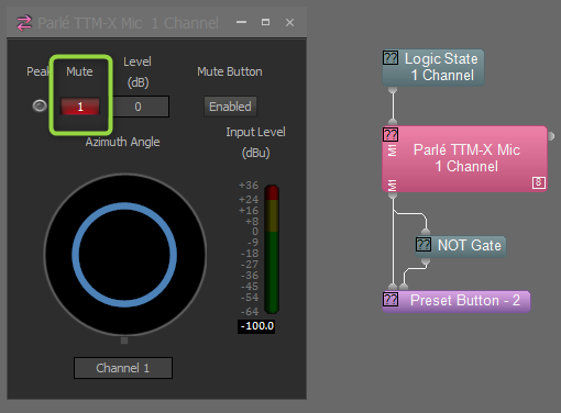
A typical example of how this might be utilized is to trigger presets based on the mute status through the use of a Preset Button block. The Preset Button block will trigger a preset on the rising edge of a logic input. In order to trigger a certain event when the microphone is muted and another event when it is unmuted, two presets will be used. The preset input directly connected to the logic output of the TTM-X block will be recalled when the mute button is activated. In order to recall a preset when the mute button is deactivated, it will need to be triggered on the falling edge of the TTM-X logic output. To do this, route the mute status logic signal through a NOT gate to invert the logic. Thus, when the microphone enters a mute state (falling edge) on the output node of the TTM-X block, the NOT gate will output a rising edge to the Preset Button.
If the mute is being controlled via a Logic State or Flip Flop gate, there will need to be corresponding presets to change the state of the logic blocks when the mute button is physically pressed. These presets will need to set the state of the Flip Flop or Logic State to match the state of the mute button.
Use TTM-X Button as Logic
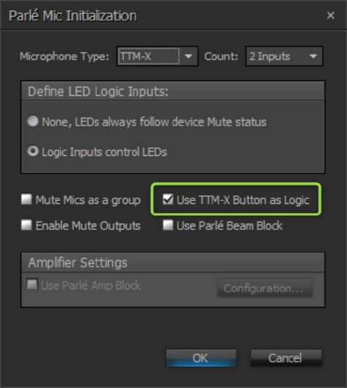
Tesira 3.17 and newer allow the TTM-X capacitive touch ring to provide a logic signal instead of muting at the microphone array. This allows the Tesira user the option to mute elsewhere in the design file and/or allow for more customized system behavior based on the TTM-X logical input. When the TTM-X block is initialized, the option can be enabled:
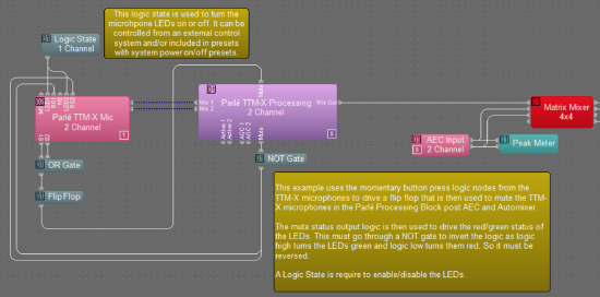
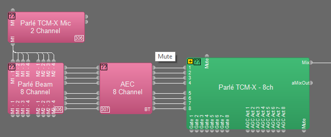
In its most basic application, the logic output can be used to mute the microphone signal downstream of the AEC processing block:
Basic post-AEC ganged mute example file.
This approach may be scaled to accommodate mute synchronization and LED indication across multiple TTM-X blocks within a system.
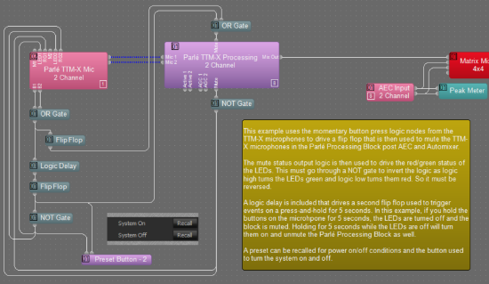
Additionally, the button logic output can be paired with a logic delay block to allow press-and-hold behaviors. The following example demonstrates the basic mute concept as well as a press-and-hold for five seconds to power down/up the system:
Press-and-hold 5s example file.
Using Third-party Control System for Mutes
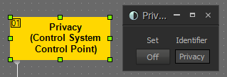
If a third-party control system is controlling or monitoring the mute state via Tesira Text Protocol, this can be managed with a Logic State block. In this example, the Logic State block with the instance tag "Privacy" can be controlled and monitored by the third-party controller with the following strings:
- Get state: "Privacy get state 1"
- Mute: "Privacy set state 1 true"
- Unmute: "Privacy set state 1 false"
- Toggle: "Privacy toggle state 1"
To change the instance tag or other block attributes, refer to the Tesira command string calculator.
Presets
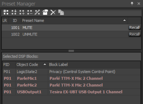
The final step is to create presets that include the mute states of all relevant blocks. In this example, we include the mute state of 2 TTM-X blocks, the logic state for the third-party control system, and the EX-UBT USB output mute (synced with a Microsoft Teams Room). This will ensure that all mute states remain in sync each time a toggle is triggered by any endpoint.
Using Parlé microphones with beam outputs
Camera tracking
Camera presets are typically selected based on logic provided in Tesira. 3rd party control systems can subscribe to logic meters in the Tesira file or the Tesira Network Command String block can be used to control a camera via IP. It is usually best to provide logic at three levels: coarse, fine and finest.
- Coarse:
- A logic meter tied to the logic outputs of the Parle Processing Block or a Gating Automixer will indicate which TCM-X/TTM-X/TCM-1 in the system is actively gated on. This can subsequently call a coarse camera preset for this area or quadrant of the room.
- Fine:
- The Parlé Beam block can be used in conjunction with Gating AutoMixer or Signal Present Meter logic outputs to monitor active beams from the TCM-X/TTM-X to trigger camera presets. This would be a good place to review the TTM-X Camera Tracking concept file.
- TCM-1 does not offer the Parlé Beam block. For 3rd party logic integration the following string creates a subscription named "P2Segments" for the segments active state of a TCM-1 called ParleMic2 with an update rate of 300 ms.
ParleMic2 subscribe segmentsActive 1 P2Segments 300
- Finest:
- This level of precision will require a 3rd party control system to gather beam angle information via TTP. The following string creates a subscription named "P1Beams" for the audio sources of ParleMic1 with an update rate of 300 ms.
ParleMic1 subscribe audioSources 1 P1Beams 300- The following TTP responses were captured via PuTTY:
- This level of precision will require a 3rd party control system to gather beam angle information via TTP. The following string creates a subscription named "P1Beams" for the audio sources of ParleMic1 with an update rate of 300 ms.
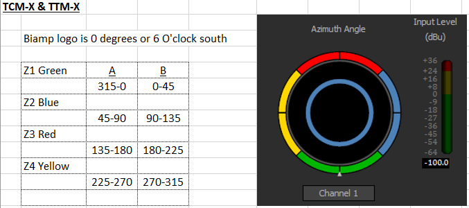
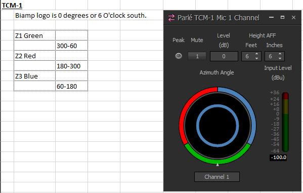
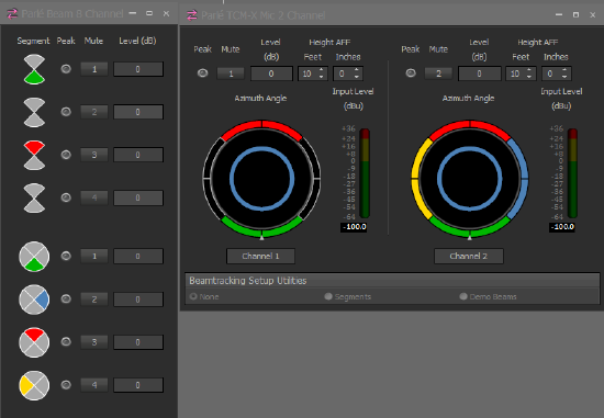
- The TTP subscription provides azimuth angle and intensity for each zone. This is the information behind the beam tracking displayed in Tesira software.
- The azimuth angles are referenced going counter-clockwise from the triangle marker in Tesira software (this is the location of the Biamp logo on the hardware).
- The intensity can be considered a confidence factor of the talker; anything above 0.5 is worth paying attention to.
- The following images help explain the segments and azimuth angles:
Locate
In Tesira v3.4, a Locate feature was added to assist with identifying physical Tesira devices on the network. This is particularly useful when attempting to identify expander devices in large distributed systems. The Locate feature can be found in several different places within the Tesira software:
- Device Maintenance
- Network toolbar
- System > Network > Locate Device
- Context menu for any DSP object (found by right-clicking on the object)
Parlé microphone array LEDs will repeatedly flash green to identify the microphone. If expander arrays are connected, a sequence of flashes followed by a pause is used to identify the connected array.
The "Power" LED on the network box will alternate between green and off when Locate is triggered from the Tesira software.
TCM-XA and TCM-1A devices will also flash the "Amp" LED on the network box alternately green and off when Locate is triggered from the Tesira software.
The TCM-XA and TCM-1A also include an audible locate function. Audible Locate runs concurrently with visual Locate, and will state the device model and channel being located. Locate messages will be played from the amplifier at the level selected in the Locate dialog, regardless of the level or mute status selected elsewhere in the software. A speaker must be connected properly to the respective amplifier output for this audio message to be heard.
The TCM-XA includes a Locate button that allows you to activate and deactivate the Locate function from the unit. This button acts as a toggle for the feature and will synchronize with the software, allowing you to turn it on from the software and then off at the unit, or vice versa.
Cue output
When tuning any room for conferencing, it is important to know what is being sent to the far end. It can be helpful to set up a local output to assess changes made to microphone settings. This output can simply be one of the analog outputs of a Tesira with an adapter wired to headphones, or the USB output of a Forte or EX-UBT connected to a PC for headphone monitoring and recording samples of the audio. 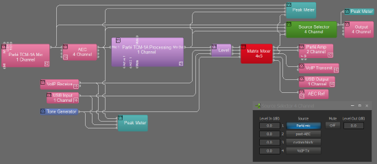
A Source Selector block with 4 or more inputs can be added to the layout. Connect the first input to the output of the Parlé microphone block (this is the raw output of the microphone array). Connect input 2 to the output of the AEC processing block (this reveals changes due to the AEC echo reduction, noise reduction, and high pass filter). Input 3 should be connected to the output of the Parlé custom library processing block (this contains a level boost, EQ curve, Gating Automixer, and AGC). If additional processing objects are added, then additional inputs should be defined for the Source Selector to incorporate these in the testing. The last input should be taken just prior to the transmit block (whether it is VoIP, POTS, USB, or analog out).
Wire the Source Selector to the appropriate output and update your hardware. Put on headphones and you should be able to choose the pick points in the mic signal chain where you'd like to compare performance. This allows the local technician an opportunity to tune the mic performance without hearing any effects of codecs on the signal. Once the local performance is verified then you can place a call and assess the transmit quality on the far end.
Voice Lift / Mix-Minus
Attempting to do local reinforcement with Parlé microphones (or with any ceiling microphone) has historically not been recommended. This is simply due to the physics of sound involved with respect to achieving acceptable reinforcement levels without feedback. However, Tesira 5.4 and newer support a feature called Parlé Presenter Lift (PPL) that offers a lift solution for some applications.
If local mix-minus reinforcement of talkers is desired, Biamp recommends the use of lavalier, handheld, or gooseneck microphones placed in close proximity to the talker's mouth. This will allow maximum gain before feedback.
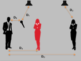 Achieving acceptable acoustic gain before feedback requires that the talker's mouth be located close to a microphone with respect to the reinforcement speakers. It is critical that the talker's reinforced voice coming from the loudspeakers be substantially less powerful at the microphone capsule than the actual talker's voice.
Ceiling microphones require relatively high input gain, as they must pick up the talker's voice at a greater distance than other microphones. In most local reinforcement applications, the reinforced audio from the loudspeaker may be equal to -- or even louder than -- the actual talker's voice at the ceiling microphone capsule. This will result in feedback if the ceiling microphone is routed to the speaker. Lowering the reinforcement level for the talker's voice to achieve acoustic stability typically results in the reinforced level being too quiet to be considered meaningful for reinforcement.
Please see our article on calculating PAG and NAG for more information on reinforcement. Each Parlé microphone array can create 3 or 4 active lobes (depending on the microphone array model) at a time, but maintains NOM internally via gain sharing, so a NOM value of 1 per pendant should be used in calculations.
The Parlé microphone array is an active beam tracking microphone, capable of tracking multiple talkers (or vocal sources) simultaneously in a 360-degree torus of coverage (more details on this can be found here). The lobes are constantly being repositioned for best coverage based on the talker's estimated position. There was no method for manually locking the lobe's coverage pattern until Tesira 5.4 which now allows locking and aiming of beams.
In a mix-minus application, the dynamically adjusting azimuth and elevation angles of the beam tracking lobes may result in unpredictable gain before feedback behavior. Multiple arrays in a single space will further increase the complexity of calculating PAG-NAG and feedback stability, as coverage lobe patterns may intersect and overlap.
Parlé microphones are not able to distinguish between a voice emanating from a loudspeaker rather than a local talker. To prevent lobes tracking to loudspeakers in normal conferencing applications, the lobes are temporarily "frozen" when the far end speaks and the microphone channel's AEC reference receives input (more details on this can be found here). In a mix-minus application, one lobe may track to the talker and other lobes may track to the reinforcement loudspeakers, further complicating the gain-before-feedback behavior.
If mix-minus sources are also sent to microphone AEC references, the microphone's beamtracking will be inadvertently "frozen" during local speech and beamtracking will not function as expected. There is no method for pre-defining where the lobe be aimed when it freezes - it simply locks at the last active talker position. Tracking resumes ("unfreezes") when the signal to the AEC reference is no longer present.

 The beam block controls provide the following: