Parlé TTM-X or TCM-X and EX-UBT or USB mute sync
This article illustrates the integration between the EX-UBT or EX-USB and Parlé TTM-X microphone mute buttons when used with an external software codec via a USB connection. This same theory can be applied to the FORTE X USB port which also supports Mute Sync.
Parlé TTM-X configuration
This feature requires Tesira firmware version 3.17 or later. The following options must be configured in the Parlé Mic Initialization.
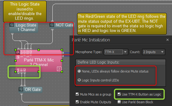
Define LED Logic Inputs
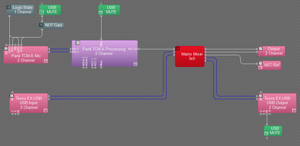
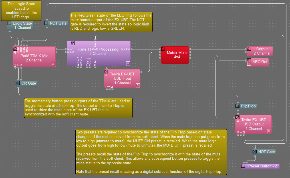
Set this to Logic Inputs control LEDs. In the default configuration, the TTM-X button ring controls the internal microphone mute and the LED ring follows the state of the mute. Change this option to de-couple the LED ring from the internal mute and allow control through logic. The LED1 and LED2 logic input nodes are used to turn the LED ring on or off. Therefore, a Logic State must be used and set to the ON state to enable the LED ring. The RG1 and RG2 logic inputs are used to switch between red and green states. A NOT gate is required to invert the logic signal in order to set the LED ring to red when the EX-UBT is muted and green when unmuted.
Use TTM-X Button as Logic
Check this box to enable additional button press logic outputs on the TTM-X input block. The B1 and B2 output nodes represent the state of the TTM-X button ring. When the button is pressed, this logic output is set high as long as the button is held. When released, it will return to a logic low state. These button presses are combined using an OR gate to toggle the state of a Flip Flop.
Presets
The mute state of the EX-UBT is set to high (muted) on a rising edge of the logic input and set to low (unmuted) on a falling edge. Therefore, a Flip Flop is used to control the state of the mute. Setting this mute will change the mute state on the computer that is connected to the EX-UBT when it is running a supported UC platform.
Note that the mute synchronization feature is not supported on all UC platforms. See Using the Tesira EX-UBT for mute synchronization compatibility with available UC platforms.
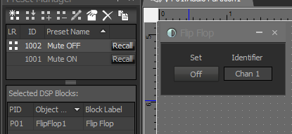
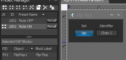
In order to synchronize the mute and LED states within Tesira when the mute state is cycled from the soft client, presets must be used in order to set the state of the Flip Flop to match. We use presets to perform the SET and RESET functions common to Flip Flops used in digital logic.
In the example file, the Mute OFF preset stores the Flip Flop in an off state.
The Mute ON preset stores the Flip Flop in an on state.
The Mute output logic node (M) on the EX-UBT block is used to recall a preset based on the state of the mute using a Preset Button block.
When the mute is activated, the output will cycle from logic low to logic high and trigger the first preset. This will recall the state of the Flip Flop to match the current state of the mute.
When the mute is deactivated, the output will cycle from logic high to logic low. However, we still need a rising edge in order to trigger the preset button input. Therefore, we take the mute state output and pass it through a NOT gate to invert the logic. Therefore, when the mute status cycles from high to low, the output of the NOT gate will cycle from low to high and recall the preset.
Example Files
Below is an example file for Parle TTM-X that contains the logic described in this article.
Below is an example file for Parle TCM-X that contains the logic described in this article.
TCM-X_EX-USB Mute Sync Example_SW411.tmf