Signal lines
This article discusses the various aspects of signal lines in Tesira, along with some tips and tricks on how to efficiently create and manage lines in a Tesira configuration. Signal lines represent the flow of audio signals or logic signals through the layout. They propagate from the output of a DSP block to the input of the next DSP block, or from the output of a logic block to the input of the next logic block.
Audio signals in Tesira propagate from left to right, and logic signals propagate from top to bottom. Inputs on a block can receive only one line apiece, however lines can fan out (a.k.a. "Y" or "wye") from a single output to multiple inputs on one or more blocks.
Ports
Ports on component blocks are large and easy to select. Each port inhabits a 10x10 pixel space, which makes grabbing connectors easy. Ports “light up” when selected, ports which are receiving line connections will "light up" as they are connected.

Shift-click on a port to quickly add a label to the port.
Crosshairs
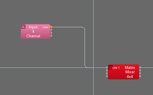
When connecting components, crosshairs make it easy to align your lines with ports. "Display crosshairs" is enabled in Tools > Options > Application Settings... > Display > Lines.
Magnification
To zoom in and out while drawing a line use the + and - keys or scrolling the mouse wheel. When not drawing a line you can zoom in and out by holding the Ctrl key and scrolling the mouse wheel.
Bends
While drawing a line, clicking will place a flex point on the line. This allows you to manually determine the line path. If you don't intervene, Tesira will automatically place the turns for you when you drag from one component block port to another.
Adding a bump-out
While in Orthogonal line mode, a bump-out can be created with just a single click on the line while holding the Alt key. To remove a bump-out, grab and drag the bump-out to realign it with the line. The line will "heal" itself.
Hold the Alt key and left-click on the line where you'd like to add a bump-out:
A bump-out is created:
Click and drag on line segments to position and size the bump-out to add visual clarity to the diagram:
On a non-Orthogonal (i.e. diagonal) line, Alt-clicking on the line will add a single flex point rather than a bump-out.
Fan out
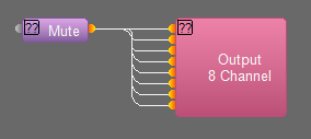
To connect one output to multiple inputs on a single block, click and hold the Shift key while drawing the line. As you approach a block with multiple inputs the line will fan out and automatically connect to all of the available ports.
To move the fan out lines as a group, hold the Shift key while you click on the lines and drag them to the desired location, place the cursor over a point which has all of the line segments of interest for the move.
Connection shortcuts
In addition to the ability to select multiple ports and pull lines manually to the next block or group of blocks, you can opt to select two or more component blocks and use the right-click "Connect Audio" wiring command. The keyboard shortcut is Shift+RightArrow.
"Connect Logic" will give similar behavior, specific to logic ports on devices. The keyboard shortcut is Shift+UpArrow.
Lines can originate from either direction. Select the blocks to be connected. When selecting more than two blocks, note that the block with green handles is always the origin for the lines. Holding the Alt key while clicking on other selected blocks will allow you to choose which block has the green handles. Right-click and select "Connect Audio" or "Connect Logic" to connect the ports.
Connect 1 block with 8 ports to 8 blocks with 1 port:
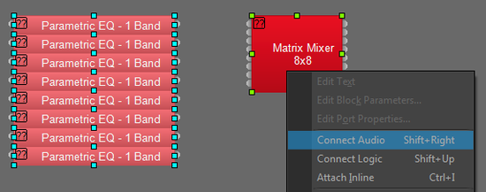
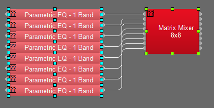
Connect to one or more blocks with a matching number of ports:
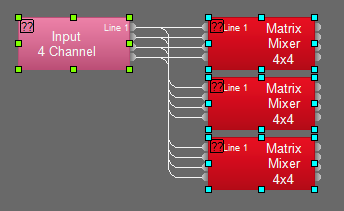
When connecting to a mismatched number of ports, it will make a "best attempt" to connect to available ports:
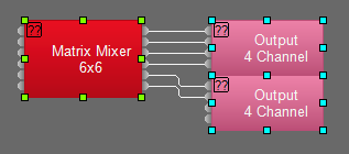
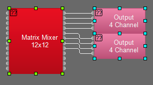
Connect components to input and output ports simultaneously. The origin block (with green handles) must be in the middle for this to work as shown below:


Note: If you attempt to connect across more than 1 component in either direction it will assume you are Y-ing the output side of the green handled object. This may have unintended consequences.
- Here the matrix mixer has connected to the (8) parametric EQ blocks on the input ports, and Y-ed its outputs ports to the 2nd matrix mixer and to the (2) 4-channel output blocks.

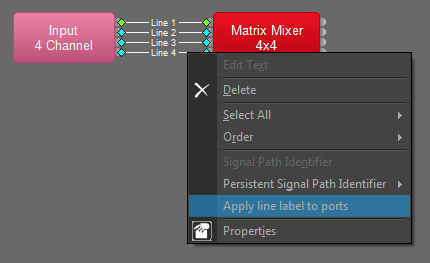
Apply line label to ports
Text applied to lines can be quickly pushed to the connected ports for easy labeling of connectors. To add text to lines, click on the line and hit the Enter key, or right-click and choose "Edit Text".
Select a line with text and right-click on it with the mouse, choose "Apply line label to ports". Labels will be pushed to the blocks at either end of the selected line segment.
- Multiple lines can be selected simultaneously.
- Lines without labels will propagate blank text to the ports.
- Labels will be retained by the blocks if the line is deleted or renamed


Attach Inline
Easily insert a component on an existing line by placing the new component’s ports on the line and selecting the right-click option “Attach Inline” or the keyboard shortcut Ctrl+i. The ports of the component must overlap the line for the Attach Inline feature to work.
This feature applies to both audio and logic components. Audio lines can only connect to audio ports, and logic lines to logic ports.
It is possible to select any number of blocks before attaching.
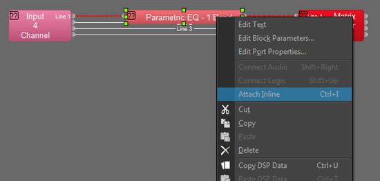

Notice that line names are copied onto each of the 2 new segments. All other line properties are passed on to the new segments as well.
Line spacing
Tesira software defaults to drawing lines in parallel on the horizontal and stacked on the vertical axes. It is easy to draw lines with parallel paths on both axes using the right and left arrow keys while drawing lines.
While lines are being drawn, hitting the left and right arrow keys will cause the lines to offset on the vertical axis for clearer layouts. The arrow keys control the direction of spread when turning corners; with the right arrow the top line leads the group, with the left arrow the top line lags the group.
Tools > Options > Application Settings > Collapsed Line Spacing determines the pixel separation of vertical lines in Orthogonal line drawing mode when the left or right arrow keys are held. This works for both audio and logic lines.
Standard lines are drawn in parallel on the horizontal and collapsed on the vertical axes:
Use the right arrow key to add space between descending lines:
Use the left arrow key to add space between ascending lines:
Using the left arrow key with descending lines produces folds.
Persistent Signal Path Identifier
The Persistent Signal Path Identifier causes a selected wire to be "illuminated" as a dashed red line showing all possible paths for audio to and from that point. It is a very useful tool for verifying signal flow through matrix mixers, for quickly trouble-shooting AEC reference paths, or resolving signal flow issues caused by inadvertent muting. It functions both while offline and online.
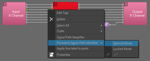
To enable the Persistent Signal Path Identifier, select or hover over a line and right-click on the mouse, then choose Persistent Signal Path Identifier > Normal Mode. Normal Mode allows you to click on other lines and the indicator will follow. Locked Mode will lock the identifier to the current line. Signal Path Identifier will illuminate the path of the wire you are currently on, and turn off when you click elsewhere in the configuration.

The signal path identifier also works on video partitions. Signal lines in yellow are video streams and red lines are audio streams on the video partition. The combo line of yellow+red indicates a video stream with embedded audio.

The signal path identifier will show a purple outline when a video signal between TesiraLUX blocks where HDCP is enabled.

Logic Simulation
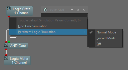
Similar to the Persistent Signal Path Identifier, the Persistent Logic Simulation allows you to test logic behavior while offline.
Right-click on a logic port to activate the simulation mode. Hold the Ctrl key and left click to select a different logic port to switch between logic circuits while in the Persistent Logic Simulation mode.
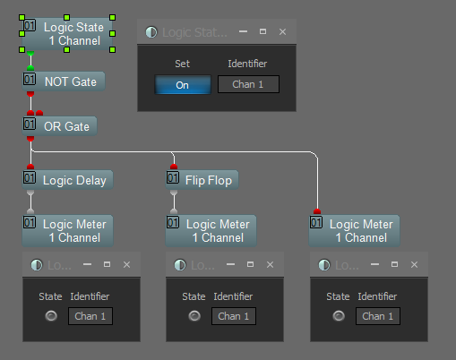
Simulation output does not trigger Presets or activate Logic Meters, rather, the logic ports “light up” in red and green to show the behavior of the logic gates in the path.
Logic State controls are used as triggering events for the logic gates in simulation mode.
Logic delays, flip flops and pass-throughs do not pass logic simulation.
