Video and network latency
Latency is the time it takes for a signal to pass from one place to another. Every component in an AV system adds some amount of latency to the total propagation time of a signal through a system. You may be concerned about latency from input to output of a single device, or from input to output of an entire system. This article will cover some latency concepts with regard to distributed audio and video systems.
Latency basics
End to end latency is a major concern for distributed audio and video systems when live images are being captured and reproduced for a local audience. Are the source and destination co-located in the same room or space? If there is appreciable delay then the audience will be aware of sync issues between the live presenter and the video displays.
The total latency from camera lens to display screen is called end-to-end latency or glass-to-glass latency. Extremely low glass-to-glass latency is considered to be below 100ms (for image based surgery, industrial, and military applications), very low would be below 200ms, low would be below 300ms or so.
Acceptable latency may be seen as a function of the application. A concert video screen should normally have “near zero” latency. But, if the average audience member is seated 150 feet from the stage and the sound takes about 133ms to travel from the speaker to the listener, then “near zero” for video display is anything below about 150ms. A surgeon moving a scalpel under a video microscope will want much faster glass-to-glass latency to ensure that cuts are seen as they are made.
When content is pre-recorded, system latency is not usually a huge concern but simultaneous playback will be critical (e.g., the same content playing on multiple displays and speakers around a room). Simultaneous playback requires delay equalization to match delivery times at endpoints, this is handled automatically by Tesira.
In audio systems, latency is typically described in milliseconds or distance (feet or meters) of delay. Frequently, DSP latency is a concern in near-field monitoring applications where the processing latency may delay audio to the point where it is perceptible to the listener.
In video systems, latency is often described in terms of frames. You must know the frame rate for this number to be meaningful since a phrase like '1.5 frames of latency' is directly dependent on the length of time each frame is displayed. 'Cinema' is typically shot at 24 fps; other common speeds are 30 fps, 50 fps, and 60 fps. At 60 frames per second, each frame lasts 1/60 of a second, which equals ~16.7 milliseconds, meaning 1.5 frames of latency at 60 fps is ~25ms. By comparison, 1.5 frames of latency at 24 fps is ~62ms.
TesiraLUX latency
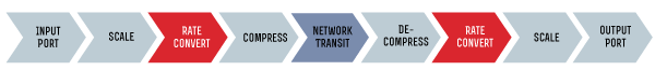
For TesiraLUX, the input to output plug-to-plug latency (sometimes referred to as the system transit latency) - which includes encoding, scaling, compression, network transit, and decoding - will take less than 25ms at 60fps.
- 1 frame if no compression is applied (16ms at 60 fps)
- less than 1.5 frames with up to 20:1 compression (25ms at 60 fps)
The exception is when you reduce the frame rate — a frame of latency will be added as the system re-clocks.
The variables in each system scenario are unique so there is no way to predict an exact value for all streams, so we guarantee the upper boundary for video stream latency is less than 25ms at 60fps. System transit latency is not impacted significantly by compression. It will be less than 25ms at 60fps regardless of whether or not the stream is compresssed.
Other major sources of latency include:
- Camera lag can be a significant component of perceived latency, ranging from 2-4 frames or more.
- Changing the frame rate will also impact latency.
- Display lag, which is typically around 1 frame.
Compression and latency
While consumers are used to the high compression ratios like those found in h.264/AVC or h.265/HEVC that are necessary for delivering video over mobile et. al. (and the increase in artifacts that come with the compression), TesiraLUX is not intended for those scenarios.
Our goal is low latency, visually lossless transport at relatively low compression ratios. Since high compression was not a design goal, we focused on more mature, less complex algorithms with well-shaped constant bit rate streams like M-JPEG.
M-JPEG is royalty-free, whereas other popular algorithms, including JPEG2000, MPEG 2, h.264/AVC, and h.265/HEVC are not royalty-free. Video codecs should be chosen on a per application basis and optimized for the targeted use. For low latency, visually lossless applications, an I-frame only codec like M-JPEG works very well.
Camera lag
4K cameras are often – but not always – the single greatest contributor to latency in a typical pro AV signal chain. By comparison the audio latency is negligible.
Many digital cameras use a charge-coupled device (CCD) for converting an electrical charge into a digital value. In a CCD image sensor, there is a photoactive region constructed from an ultra-thin layer of silicon, followed by an underlying transmission region made out of a shift register (nerd out on Wikipedia if you like).
An image is projected through a lens onto the photoactive region, causing each capacitor (there’s one capacitor for each pixel) to accumulate an electric charge proportional to the light intensity at that location. An A/D converter measures the charge and creates a digital signal that represents the value of the charge at each pixel. Then, an onboard signal processor interpolates the data from each pixel to create natural color. On many cameras, it’s possible to see the output on a flip-out LCD at this stage. Lastly, some cameras may perform a preset level of compression on the data before outputting the video stream.
A 4K image contains more than 8 million pixels per frame, each with its own chroma and luminance data, and 4K cameras can very easily introduce 3-4 frames of latency (51-66ms at 60fps) before the video signal even reaches the input port of the IDH-1 encoder. Adding two frames of TesiraLUX system transit latency to the calculation brings the latency to approximately 84-99ms. Finally, add about one frame (or more, depending on the display model and stream parameters.) for display lag at the output. Display lag can range from 10ms to 100ms or more depending on the monitor and its settings. This results in an overall video latency of 101-116ms.
Lip sync
Lip sync of audio to video is a very important component of system design. In general, the audio can arrive up to 45 milliseconds before the video, or up to 125 milliseconds after the video. Outside of this window of +45 to -125 milliseconds1, it will begin to become noticeable and distracting for most people. This is because the human brain is used to audio signals arriving after video signals (since sound moves much slower than light), so it is much more tolerant of audio lagging the video.
"...subjective evaluations show that detectability thresholds are about +45 ms to -125 ms and acceptability thresholds are about +90 ms to -185 ms on the average..."1
"... should be kept within the values +22.5 ms and -30 ms..."1
As a functional specification, TesiraLUX calls for the presentation of audio relative to video to be between 15 milliseconds advanced (leading) and 25 milliseconds delayed (lagging) relative to the video (often stated as a range of +15 ms to -25 ms of video-to-audio delay.) This means that the audio will not shift relative to video beyond the +15ms to -25ms range within the TesiraLUX environment, it cannot control the behavior of devices outside of TesiraLUX.
With a potential 101-116ms of video transmission latency (in the example in the above section), audio may need additional delay to be inserted to match the video latency if it has not already been compensated for by the capturing device.
For remote monitors positioned at a distance from a live audio/video source, TesiraLUX offers up to 64ms (4 frames at 60fps) of audio delay in both the IDH-1 and OH-1 endpoints. In most cases the OH-1 will be the preferred point of application as the monitor distances from the origin will vary, and because display lag will vary by monitor model.
1 ITU-R publication BT.1359 recommends the relative timing of audio and video for broadcasting.