GPIO-1 wiring schematics
This article explains how the various GPIO-1 inputs and outputs can be wired.
GPIO-1 inputs
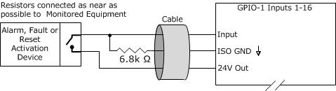
1. High Range Monitored Input – Active High - 24VDC Locally Sourced
Notes: Vocia software configured as High Range Monitored - Active State High. Circuit shown in Low State.
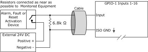
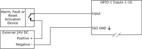
2. High Range Monitored Input – Active High - 24VDC Externally Sourced
Notes: Vocia software configured as High Range Monitored - Active State High. Circuit shown in Low State.
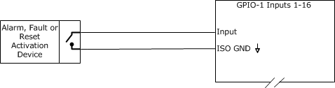
3. High Range Unmonitored Input – Active High - 24VDC Locally Sourced
Notes: Vocia software configured as High Range - Active State High. Circuit shown in Low State.
4. High Range Unmonitored Input – Active High - 24VDC Externally Sourced
Notes: Vocia software configured as High Range - Active State High. Circuit shown in Low State.
5. 5V TTL Logic Control Input
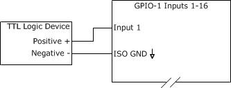
Notes:
• Low Voltage = 0 – 0.8 VDC. Logic High = 2 – 5VDC.
• If configured as Active State High Alarm/Fault/Reset triggers when voltage transitions from Low to High.
• If configured as Active State Low Alarm/Fault/Reset triggers when voltage transitions from High to Low.
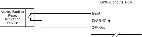
6. Contact Closure Mode
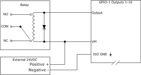
GPIO-1 outputs
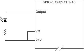
1. Outputs Driving a LED Powered from GPIO-1 24V DC Out
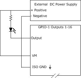
2. Outputs Driving a LED Powered Externally
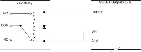
3. Outputs Driving a Relay Powered From GPIO-1 24V DC Out
4. Outputs Driving a Relay Powered Externally