Constant-voltage speaker systems
Manufacturing amplifiers for constant-voltage (CV) systems is a considerable part of Biamp’s product history. The use of constant voltage speaker lines brought many advantages for the distribution of speakers in large spaces and is still the recognized standard, while the main principle hasn’t changed for decades. Meanwhile, amplifier technologies have improved and with the release of Vocia, the constant-voltage speaker network takes place in critical life-safety applications, such as voice evacuation systems.
This tech note covers some of the fundamentals of constant-voltage speaker networks and explains how to use Biamp’s amplifiers to achieve best performance and reliability for distributed speaker systems.
Basics
The most important aspect of a constant-voltage system is that all connected amplifiers and speakers are referenced to a constant-voltage value (70.7V or 100V) at full output level (0dB). In comparison to low impedance (LoZ, 4 – 16Ω) systems, a constant-voltage system brings a lot of advantages in designing and installing distributed speakers.
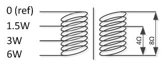 |
Constant-voltage utilizes audio transformers to adapt both impedance levels. Audio transformers usually provide different taps to set up the power taken from the speaker line by the primary coil. With each step the power doubles, which corresponds to a level increase of +3dB.
In many standard applications, the audio signal coming from a power amplifier will be transformed to higher impedance through a built-in or an external audio transformer. Once the audio signal is transformed to higher impedance (higher voltage for the same output power), each speaker must be equipped with a transformer as well, to adapt (step down) from CV to LoZ:
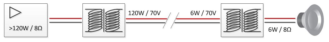
Fig. 2 Block diagram of a single CV speaker line
Constant-voltage vs. low impedance
The advantages in using constant-voltage are:
- Large quantities of speakers can be wired in parallel, limited only by available amplifier power
- Higher voltage enables long cable runs between amp and speakers with reduced power loss
- Low current reduces the required diameter of the speaker cable
- Easy to design and to install, use of low-cost standard cabling
- Different speaker types with different power requirements can share the same speaker line at the same time
In the following drawing, the speaker line requires an amplifier with at least 31Watts of amplifier power. The fact that the amplifier is capable of 120Watts output power does not mean that speakers will be damaged. It can be understood as headroom: An oversized amplifier will allow the option to add more speakers to the line at any time if desired.
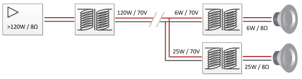
Fig. 3 Block diagram of parallel CV speaker lines
In summary, all of these advantages translate to versatility, which is clearly the strength of CV speaker systems. But there are also shortcomings involved with using a CV system; these are related to audio quality:
- Limited frequency range, particularly in low frequency response
- Increased distortion, especially in high frequency range
- Lowered damping factor
- Overall loss in performance and sound accuracy
These characteristics are limiting the range of applications for CV systems. CV will be the right choice in wide spaces, for distributed audio environments, background music applications and paging.
When it comes to sound reinforcement systems with an increased demand for music performance, a LoZ speaker system should be chosen. To get both advantages out of one system, modern amplifier technologies make it possible to drive CV and LoZ speakers with one device. In the following example a Stereo front PA, a pair of delay speakers and a CV speaker line for audio distribution in the whole building is facilitated by one multichannel amplifier.
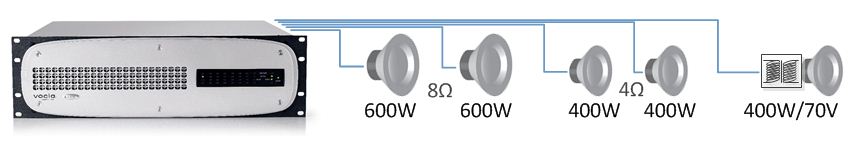
Fig. 4 Application Example with a VA-8600
Impedances
The following table lists the load impedances presented to the amplifier depending on the power drawn by connected speakers. The Power (W) column represents the sum of the transformer taps of all speakers connected to the amplifier output.
| Power (W) | Load @ 70.7V | Load @ 100V |
|---|---|---|
| 3 | 1666Ω | 3334Ω |
| 6 | 833Ω | 1667Ω |
| 10 | 500Ω | 1000Ω |
| 50 | 100Ω | 200Ω |
| 100 | 50Ω | 100Ω |
| 150 | 33.3Ω | 66.7Ω |
| 200 | 25Ω | 50Ω |
| 300 | 16.7Ω | 33.4Ω |
| 500 | 10Ω | 20Ω |
| 600 | 8.3Ω | 16.7Ω |
Table 1: Load impedances for 70V and 100V line voltage
It is recommended to check a speaker line’s impedance with an impedance meter before it will be connected to an amplifier. Most impedance meters on the market use a 1kHz sine wave tone to read the actual load of the speaker line. Advanced functions of an impedance meter can be a variable measuring tone frequency or sweep. The measuring tone can usually be heard on all connected speakers, which makes it a helpful troubleshooting tool.
Note that a coil’s impedance will increase in relation to frequency. That also applies to the primary coil of audio transformers. Especially when a couple of them are wired in parallel, this may result in critical impedances at lower frequencies. It is recommended, to always use a high-pass filter when driving constant-voltage speaker lines, it will prevent the amplifier from overheating or reporting short circuit errors. Most constant-voltage amplifiers have a built-in high pass filter on each output.
Cable Loss
Even though constant-voltage can be transported over long distances, there is still a certain amount of cable loss that needs to be considered. As in all electrical connections, the loss of power will increase when increasing the distance, increasing the load impedance, or decreasing the conductor diameter. And there is another factor that should be taken seriously: the temperature. Especially in outdoor installations, where temperature changes have a direct influence on the conductor, the speaker line’s impedance can easily drift by 10%. This should be considered especially when impedance monitoring functions are in use.
The following table gives a brief overview on maximum speaker line lengths. The calculation of each cable length refers to a loss which won’t exceed -1dB or 20% of power. The following numbers assume a line voltage of 70.7V. Note that 100V lines are capable of running twice the distance to get the same loss as a 70V line.
| Power | 10AWG (5.27mm²) | 12AWG (3.3mm²) | 14AWG (2.08mm²) | 16AWG (1.31mm²) | 18AWG (0.79mm²) | 20AWG (0.51mm²) |
|---|---|---|---|---|---|---|
| 50W | 12795 ft (3900 m) | 8005 ft (2440 m) | 5052 ft (1540 m) | 3150 ft (960 m) | 1903 ft (580 m) | 1230 ft (375 m) |
| 100W | 6398 ft (1950 m) | 4003 ft (1220 m) | 2526 ft (770 m) | 1575 ft (480 m) | 951 ft (290 m) | 617 ft (188 m) |
| 150W | 4265 ft (1300 m) | 2657 ft (810 m) | 1673 ft (510 m) | 1050 ft (320 m) | 640 ft (195 m) | 410 ft (125 m) |
| 200W | 3182 ft (970 m) | 1995 ft (608 m) | 1263 ft (385 m) | 787 ft (240 m) | 476 ft (145 m) | 308 ft (94 m) |
| 300W | 2133 ft (650 m) | 1329 ft (405 m) | 837 ft (255 m) | 525 ft (160 m) | 318 ft (97 m) | 207 ft (63 m) |
| 500W | 1280 ft (390 m) | 801 ft (244 m) | 502 ft (153 m) | 315 ft (96 m) | 190 ft (58 m) | 125 ft (38 m) |
| 600W | 1066 ft (325 m) | 663 ft (202 m) | 420 ft (128 m) | 262 ft (80 m) | 160 ft (48 m) | 102 ft (31 m) |
Table 2: Power loss on different cable gauges
NOTE: The distances shown are individual conductor length. Loudspeakers cables should always be a twisted pair, so divide the above distances by two for cable run lengths.
Every cable is different and so are the results of any cable loss calculation. As some installation wires consist of copper-aluminium alloy, the specific conductor resistance may differ between different cable types and manufacturers. The only way to get reliable numbers will be to use the data provided by the cable manufacturer. This table was calculated with the specific resistance of copper, which is 0.0172Ω per mm² per meter.
Constant-voltage in Vocia and Audia
With Audia Fusion and the VA-8600 Amplifier, Biamp introduced high-performance multichannel amplifiers, which are capable of adapting their output voltage directly to low impedance speakers and constant-voltage speaker lines, without the need for output transformers. This method of transformerless interfacing is called Direct Drive.
In Vocia software, the type of speaker connection can be selected in the amplifier’s control dialog. All speaker output settings are set on the lowest voltage (4Ω, 100W) by default.

Fig. 5 Channel output setting on a VA-8600
The Vocia amplifiers VA-2060 and VA-4030 series use output transformers to adapt the connected load. Therefore, each speaker output channel is coupled to an output load selector (Channels 1-4 from right to left):
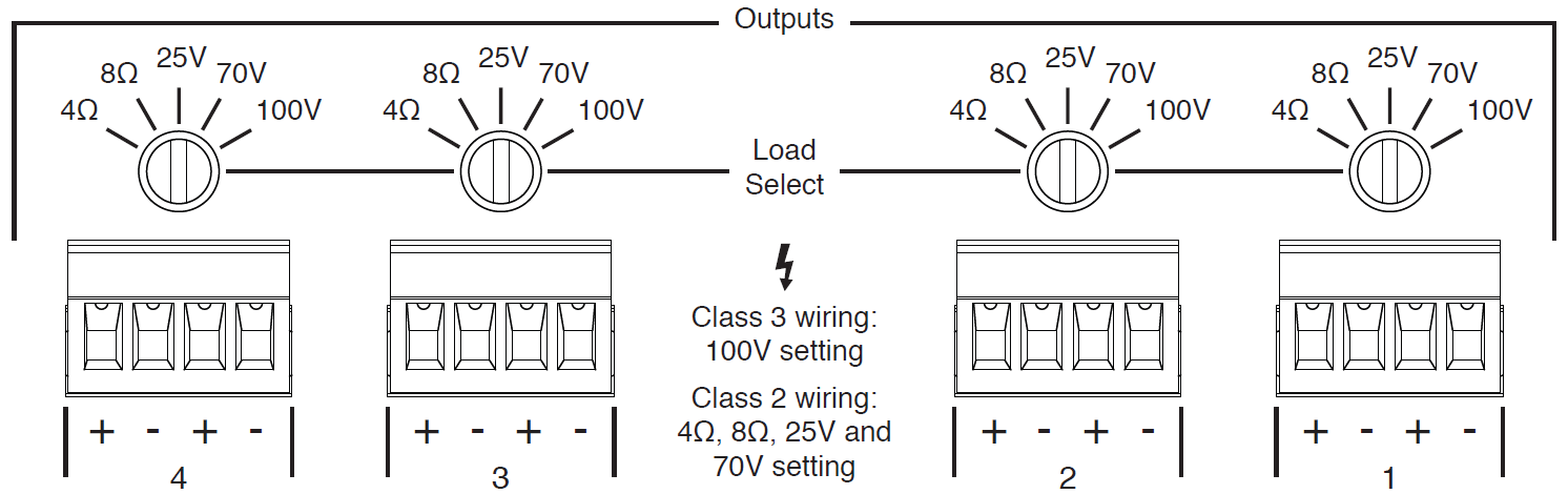
Fig. 6 Channel output setting on a VA-4030
To use the Audia Fusion multichannel amplifier inside an Audia configuration layout, the Fusion output block must be selected in the I/O Menu. Right after adding the block to the workspace, the block's initialization dialog allows all necessary settings to be applied to the amplifier output(s):
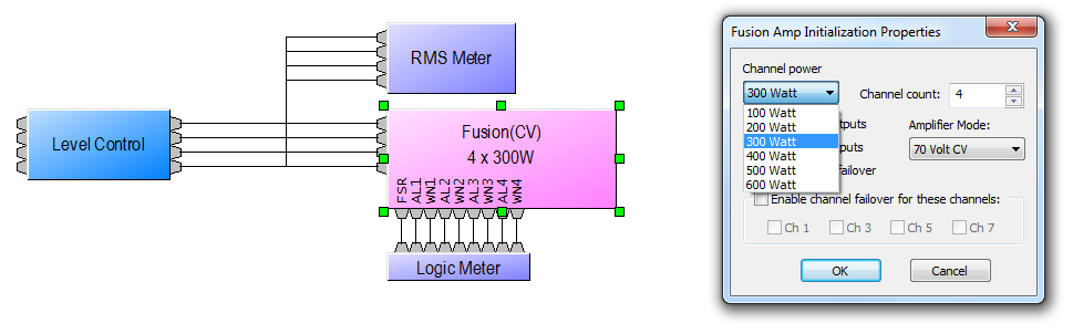
Fig. 7 Channel output setting on Audia Fusion
Speaker line monitoring
Both AudiaFusion and all Vocia amplifier models offer speaker line monitoring functions. AudiaFusion monitors impedance by directly measuring output voltage and current, while a Vocia amplifier will send out inaudible signals that are detected by an End of Line Device (ELD-1). This method of line monitoring works for all types of impedances and power settings.
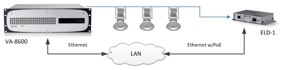
Fig. 8 Application Example with a VA-8600
Any connection problem in the speaker line will interrupt the communication between the amplifier and the ELD-1. Once an error has been detected, it will be displayed in Vocia software or, in order to comply with life safety standards, it will be reported by the Life Safety Interface (LSI-16, LSI-16e).
The way speaker line monitoring works in Audia Fusion is different, as it works with a live analysis of the actual current in relation to frequency at the speaker output of each channel. This measurement can be displayed as a graph in Audia software:
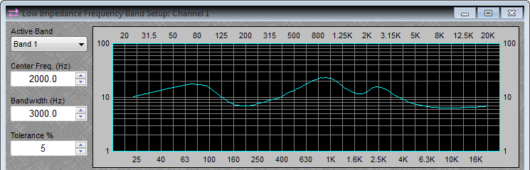
Fig. 9 Impedance measurement in Audia Fusion
To get a permanent current read-out on the amplifier output, a signal with sufficient level must be present all the time. To facilitate monitoring of a speaker line’s integrity, inaudible, high-frequency tones can be mixed into the output signal. The monitoring itself happens in one or multiple bands. For instance, if only a pilot tone of 20kHz shall be monitored, a band can be set to 20kHz, with a very narrow bandwidth. If a larger frequency spectrum needs to be monitored, the bandwidth can be expanded and multiple bands can be used.