Connecting a Clockaudio microphone desk stand to an EX-LOGIC
One popular application for the Tesira EX-LOGIC is to interface with conferencing microphones that feature mute switches and LED indicators, and Clockaudio is a leading manufacturer of such microphones. This article describes how to physically connect Clockaudio table-top microphone desk stands (such as the S135, S140, S155, and S157) to a Tesira EX-LOGIC expander.
This article specifically deals with Clockaudio table-top microphone desk stands with a 5-pin or 7-pin XLR connector. For other Clockaudio products that use an RJ45 connector, see Connecting Clockaudio microphones and mounts to an EX-LOGIC.
Goal
After completing the steps in this article, you will be able to connect a Clockaudio table-top desk stand to a Tesira EX-LOGIC. This will allow your Tesira configuration to control the LED on the desk stand, and it will also allow the switch on the desk stand to control functions within your Tesira configuration (like mic muting).
The desk stand uses phantom power to power its LED, so no external power supply is required. One exception is the S157, which includes the ability to power a halo ring on an attached microphone. Power for the halo ring must come from an external power supply, as detailed in the diagrams below.
Pinout
Clockaudio desk stands have a mute switch and a single-color LED. The desk stand has either a 5-pin XLR connector or a 7-pin XLR connector (S157 only), with the following functions assigned to each pin:
| Pin | Function |
|---|---|
| Pin 1 | Ground |
| Pin 2 | LED contact |
| Pin 3 | Audio (-) |
| Pin 4 | Switch contact |
| Pin 5 | Audio (+) |
| Pin 6 (S157 only) | Halo Voltage + |
| Pin 7 (S157 only) | Halo Voltage - |
Wiring
An EX-LOGIC has 16 Logic I/O connections. Each Logic I/O can either be used as an input or an output (but not both), and input/output status of each terminal is determined by the Tesira programming. The diagrams in this article arbitrarily show logic inputs as channels 1-8, and logic outputs as channels 9-16, but the Tesira programming can define the inputs and outputs differently.
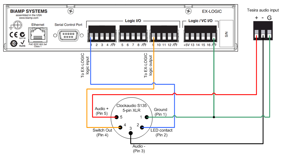
5-pin XLR
The diagram below shows how to connect a Clockaudio desk stand with a 5-pin XLR to an EX-LOGIC. This diagram applies to the Clockaudio S135, S140, and S155.
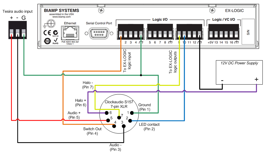
7-pin XLR
The diagram below shows how to connect a Clockaudio desk stand with a 7-pin XLR to an EX-LOGIC. This diagram applies to the Clockaudio S157.
Mic options
The Clockaudio desk stands also have various options to change the behavior of the switch and LED. To set the options, hold down the mute button while applying power to the mic (either by plugging the mic cable in, or by switching on phantom power). The LED will flash for 2 seconds to indicate that you are in setup mode. Then, press the switch 1-4 times (the interval between presses must be less than 1 second), depending on which option you want to set (see the table below).
Once you have selected the option you want to change, the LED will blink once for mode one or twice for mode two to indicate the mode to which that option is currently set. Then, you can press the switch either once or twice to set the option to the desired mode. See the table in Figure 4 below for the four available options and their modes.
After setting an option, the LED blinks for 2 seconds again, indicating that it is ready for you to select another option. Otherwise, if you don’t press the switch for longer than 5 seconds, the unit will exit setup mode and resume normal operation.
| Option | Mode 1 (Press once) | Mode 2 (Press twice) |
|---|---|---|
| 1 - Momentary/Latching Switch | Momentary | Latching |
| 2 - Normally Off / Normally On | Normally Off (Push to talk) | Normally On (Push to mute) |
| 3 - Activation Tone Off/On | Tone Off | Tone On |
| 4 - Local Mute / Remote Mute | Local Mute (S135 mutes the mic signal) | Remote Mute (Tesira mutes the mic signal) |
For instance, to set the desk stand to Remote Mute mode, first press the button four times to select option 4, then press the button twice to select mode 2.
Further reading
- For information on other Clockaudio products that use an RJ45 connector, see Connecting Clockaudio microphones and mounts to an EX-LOGIC.
- EX-LOGIC programming
- Muting microphones with logic