Muting microphones with logic
When using microphones with mute switches in an audio system, it is often preferable to wire the mute switches and LED wiring back to the Tesira system (either via EX-LOGIC(s) or to the GPIO connectors on a server or TesiraFORTÉ). This allows for the microphones to be muted in the DSP instead of at the microphone (which is especially preferable when AEC is being used), and allows for greater control and more flexibility with the muting functionality.
This article provides examples for how to program different common scenarios that use mic muting logic. For a refresher on basic logic functions, see EX-LOGIC programming.
Normally-closed or normally-open
Mic mute switches can be normally-closed (meaning that they normally create a short circuit, and then create an open circuit when the mute switch is pressed) or normally-open (meaning that they normally create an open circuit, and then create a short circuit when the mute switch is pressed). When connecting these mute switches to a Tesira system, it is important to know whether the switch is normally-open or normally-closed.
On a Tesira logic input, a short circuit will create a low logic signal (i.e., off), and an open circuit will create a high logic signal (i.e., on). Therefore, normally-closed mute switches create normally-low logic signals, and normally-open mute switches create normally-high logic signals.
Tesira logic blocks usually work best with normally-low logic signals. So, if you are working with normally-open switches, you'll usually need to either put the logic signal through a NOT gate, or just enable the Invert button in the Logic Input block.
Push-to-mute, push-to-talk
 The simplest forms of muting are push-to-mute and push-to-talk. Push-to-mute means the mic is always unmuted, unless you are holding down the mute button. Push-to-talk is the opposite: the mic is always muted, unless you are holding down the mute button. This example assumes that the mic mute switch is a momentary switch.
The easiest way to create push-to-mute or push-to-talk functionality is to connect the logic signals to a Mute block that has its Control Inputs enabled. The Mute block will mute a channel when its incoming logic signal is high, and unmute it when the logic signal is low. So, assuming the mute switch is normally-open, connecting the logic directly from the Logic Input to the Mute block will create push-to-talk functionality. To switch that to push-to-mute functionality, just enable the Invert button in the Logic Input block (or put the logic signal through a NOT gate).
Latching mute
 Latching (or "toggle") mutes are more common than push-to-mute or push-to-talk. A latching mute means that the mute state toggles each time the mute switch is pressed, and stays latched in that state until the mute switch is pressed again. However, most microphone mute switches are not toggle switches, they are momentary. So, assuming the microphone has a momentary switch, that momentary logic signal must be converted to a latching logic signal.
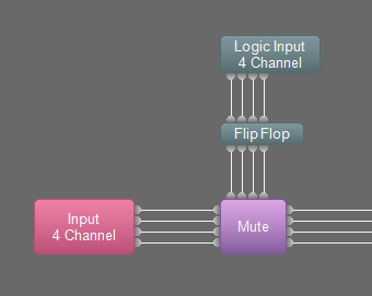
The Flip Flop block is used to convert momentary logic signals to latching logic signals. Whenever the Flip Flop senses a low-to-high logic transition on its input, it toggles its output. So, to convert from momentary to latching, just run the signal through a Flip Flop, and then connect it to a Mute block.
Controlling LEDs
 Some microphones feature one or more LEDs to indicate the current mute state. LEDs are generally connected to Logic Outputs on an EX-LOGIC or the GPIO port of a server or TesiraFORTÉ.
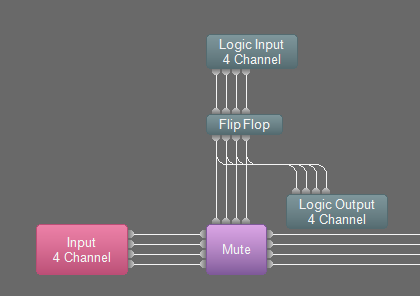
If a microphone has a single-LED, it is usually turned on when the mic is muted, and turned off when it is unmuted (although it can be configured to work in the opposite way as well). To control the LED, simply take the same logic signal that is connected to the Mute block, and also connect it to the Logic Output. If the LEDs are working opposite to the way you want (i.e. on when they should be off, off when they should be on), then enable the Invert button in the Logic Output block.
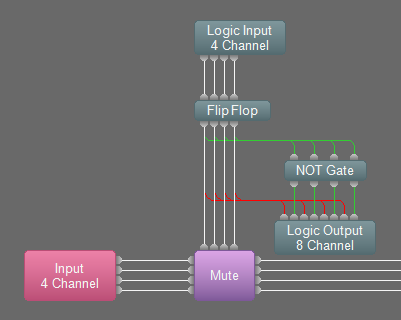 If a microphone has two LEDs (most often red and green), then usually the green LED is on when the mic is unmuted, and the red LED is on when the mic is muted. Programming this behavior requires a little more sophistication. In this case, the Logic Output connected to the red LED will be connected to the same signal that is connected to the Mute block. The Logic Output connected to the green LED will also be connected to the same signal that is connected to the Mute block, but only after that signal is put through a NOT gate. This will ensure that only one LED color is on at any one time. If the LEDs are working opposite to the way you want (i.e. red when they should be green, green when they should be red), then enable the Invert button in the Logic Output block for all of the LED logic outputs.
Tesira release 3.13 and later allow logic outputs on mute blocks. This logic output can also be used to display mute state with LEDs:

Mute all microphones
 In this example, the desired behavior is as follows: when any mute switch is pressed, it mutes/unmutes all microphones at the same time. This is useful if you don't need independent control over the mute state of individual microphones, but want a convenient place to mute/unmute all of the room's microphones.
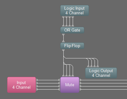
To accomplish this, an OR gate is used to combine all of the logic signals into one signal. Then, the output of the OR gate is connected to the Flip Flop and Mute block, and optionally connected to Logic Outputs if LEDs are being utilized. If you're using a ganged Mute block (with a "G" in the corner), then connect the OR gate to the single logic input on the Mute block. Otherwise, fan the logic signal out to all of the logic inputs on the Mute block.
Note: it is essential that the mute switches are momentary in this case, they cannot be latching switches. If using a latching switch, the signal must be converted to momentary. Also, it is essential that the logic signals going into the OR gate are normally-low signals. If they are normally high, then the mute state won't change when the buttons are pushed. If the mute state isn't changing when you push the button, try enabling the Invert button on all of the Logic Inputs.
Third-party Control system and UC integration
When the audio system includes a control system that is able to mute and unmute the microphones, it is important to ensure that the control system remains properly synchronized with the system. There are a number of different ways to integrate a control system:
Control system and mute switch
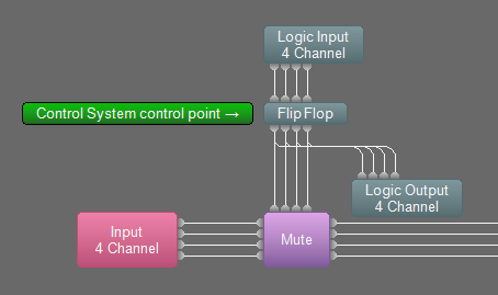 If the desired operation of the system includes the ability to mute from the microphone and mute from the control system, then the system needs to be configured a bit differently. To set up this configuration, connect the Logic Inputs through a Flip Flop, and then connect the Flip Flop to both the Mute block and the Logic Output block that drives the LEDs.
The trick to the control system integration is to make sure that the control system is controlling the Flip Flop block, not the Mute block. As long as the control system is controlling the Flip Flop block, then the mute state and the LEDs will stay in sync. If the control system needs accurate feedback for the mute state, it can subscribe to the mutes states of the Mute block.
USB-HID mute synchronization
As Unified Communications engines become the norm for videoconferencing and huddle spaces, the EX-UBT or FORTE-X devices are commonly connected via USB as the audio peripheral for the UC appliance. These Biamp products offer USB-HID mute synchronization as supported by the UC application.
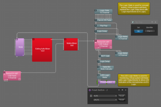
In a sense, the UC engine becomes the control system for the room because the user interface is the Teams/Zoom/etc. GUI presented on a touch surface at the table. If the audio system includes table microphones with momentary logic switches, a challenge presents. Mixing the momentary logic switches with the latching USB-HID mute logic makes synchronization a bit tricky.
The shown block arrangement is a solution to the scenario. The Preset Button includes a Mute and UnMute preset. The Mute preset sets the Flip Flop On and the UnMute preset clears the Flip Flop.
Individual mute from mic, global mute from control system
Another common scenario is to allow each microphone to mute/unmute itself independently from its mute switch, and only allow the control system to globally mute and unmute all microphones. This can be accomplished using the exact same configuration as shown in the example immediately above ("Control system and mute switch can mute"). The only change will be that two presets will need to be created: one to turn all of the Flip Flops on (the "mute" preset), and another to turn all of the Flip Flops off (the "unmute" preset). And, instead of programming the control system to control the Flip Flop gate directly, the control system should be programmed to recall each of the two presets.
Remember mute state during global mute
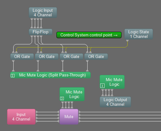 When implementing a global mute as described in the section immediately above, sometimes it is desired to have the microphones return to their previous mute state when the global mute is over. This can be accomplished by putting a 2-channel OR gate between each channel of the Flip Flop and the Mute block as shown in the screenshot. The second channel of each OR gate is driven from a single Logic State block. The control system is programmed to turn the Logic State block on and off to do a global mute. When the global mute is over and the Logic State is turned off, the previous mute states are restored.
Mute lockout
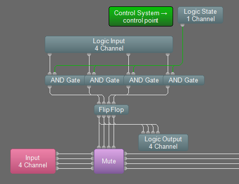 There may be some cases where the microphone buttons must be dynamically deactivated. In other words, the control system can temporarily "lockout" the microphone mute switches so that they no longer can change the mute status. To set up this configuration, an 2-channel AND gate must be inserted between each Logic Input channel and Flip Flop block, as shown in the screenshot. The Logic State block is connected to the second input of each AND gate. The control system is programmed to control the Logic State block. When the Logic State block is turned off, the mute switches will be locked out (i.e. deactivated). When the Logic State block is turned on, the mute switches will function again.
Remember mute state and mute lockout
 The two examples above can be combined, such that when the global mute is active, the mute switches are locked out so that they cannot be used to inadvertently change the "memory" of their mute state during the global mute. The screenshot to the right shows the correct order for the logic blocks (click to enlarge screenshot).
Long press mutes all mics
Another popular trick is to perform a different function when the mute switch is held down for a few seconds. In this example, the mics will be configured to toggle their mute state normally when the mute button is pressed briefly, but when the mute button is held down for 2 seconds, all mics will mute.
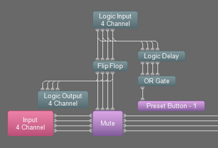
The easy way to set up this functionality is to use a Logic Delay block, an OR Gate, and a Preset button as shown in the screenshot. The path through the Flip Flop block provides the normal individual muting, and the path through the Logic Delay provides the global muting after 2 seconds. Connect the blocks as shown in the screenshot. Open the Logic Delay block and set each On Delay to 2000ms, and leave each Off Delay at 0ms. Create a preset that turns all of the Flip Flop channels on. Open the Preset Button block, and load that preset into it. That way, whenever any of the mics holds down its button for more than 2 seconds, the preset will get recalled and all mics will mute.
Long press, the hard way
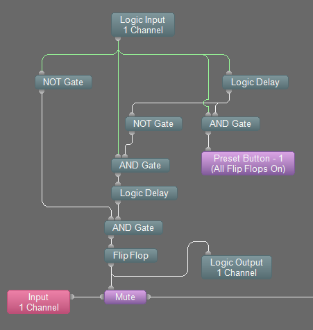 One problem with the "easy way" described above is that when you intend to do a long press to mute all mics, your mic changes its mute state immediately upon being pressed, and then all mics mute after you hold it down for 2 seconds. In some cases, this is not desirable, because the mic being used might become unmuted briefly before all mics are muted. While this problem is solvable, the logic required to solve it is complicated. See the screenshot for the required logic for one microphone. In that example, the upper Logic Delay should have an On Delay of 2000ms, and an Off Delay of 0ms. The lower Logic Delay should have an On Delay of 0ms, and an Off Delay of 100ms.
Integrating Shure MXA-Mute
The MXA-MUTE is a network-based logic mute button accessory with built-in LED halo. Since this is a network-based device, the Biamp Network Command String block can be used. The MXA-Mute's default behavior is a toggle with local LED feedback. The NCS block can track the toggle muted state to call a privacy mute within the Tesira DSP file. Conversely, HID mute synchronization via EX-UBT or USB-X can be used to call privacy mute presets within the Tesira file and thus change the toggle state of the MXA-Mute as well. If the system design includes microphones such as TCM-X or MXA-910/920, the LED indicators on these devices can be controlled for appropriate privacy mute state indication. The following Tesira Processing Library includes several NCS block and block assembly solutions that can help integrate MXA-Mute control into Tesira:
The API output for the MXA-Mute also provides explicit status for the momentary button. This can be used for Long Press applications as detailed previously in this article.