Connecting Clockaudio microphones and mounts to a Logic Box
This article specifically deals with Clockaudio products that have a 5-conductor cable terminated to an RJ45 connector. For Clockaudio table-top desk stands with XLR connectors, see Connecting a Clockaudio microphone desk stand to a Logic Box.
Goal
After completing the steps in this article, you will be able to connect a Clockaudio microphone or mount to a Biamp Logic Box. This will allow your Audia or Nexia configuration to control the LED's on the device, and it will also allow the microphone's switch to control functions within your Audia or Nexia configuration (like mic muting). Some Clockaudio products have multi-color LED's (red/green), others have single-color LED's; some have mechanical mute switches, others have touch-sensitive switches. Regardless of the model used, all Clockaudio products that have an RJ45 cable use the same wiring scheme, described below.
Note that the Logic Box cannot supply the DC power required to activate any LED's connected to it. Therefore, an external power supply is required to power the LED's. This power supply is not included with either the Clockaudio product or the Biamp Logic Box.
Conductor colors
Each Clockaudio device has a 5-conductor cable tail attached to it, which is terminated to an RJ45 connector. When connecting the device to a Logic Box, the RJ45 connector is sometimes cut off. The 5-conductor cable tail is comprised of the following colors:
| Conductor Color | Function | RJ45 Pin Number |
|---|---|---|
| Red | Red LED | 2 |
| Blue | Ground | 3 |
| Brown | DC Voltage + | 4 |
| Yellow | Switch contact | 5 |
| Green | Green LED | 6 |
Older models of many Clockaudio products had different color conductors than the ones listed above (and in some cases, they may have had different DC voltage requirements as well). Check the included Clockaudio documentation to confirm the wiring scheme and voltage requirements.
Wiring
A Logic Box has 20 Logic I/O connections. Each Logic I/O can either be used as an input or an output (but not both). Each microphone's LED conductor (up to 2 per mic) must connect to a separate logic output on the Logic Box, and each switch contact must connect to a logic input.
Clockaudio devices require a 12V power supply. The diagrams below shows how to wire a Clockaudio device (with red and green LED's) to a Logic Box using a 12V DC power supply:
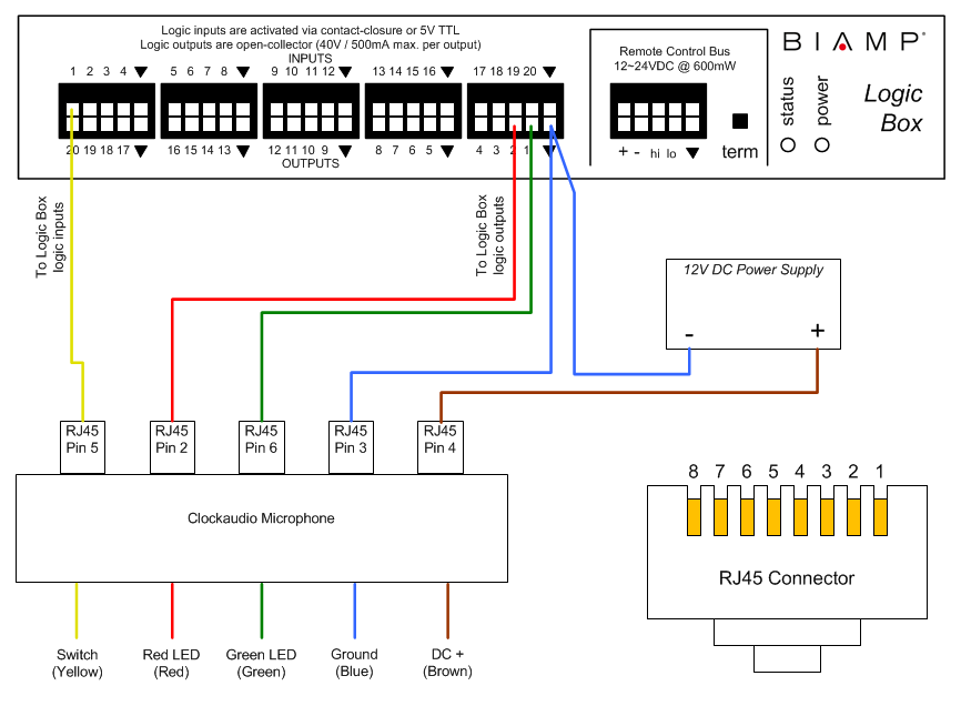 Click the diagram for a full-size view. This diagram applies to the following microphone models:
- CH32 / CH32W
- TS001 / TS001W
- SM80S-PTT / SM80SN-PTT
- SM80S-Latch / SM80SN-Latch
- SM80S-RF-PTT / SM80SN-RF-PTT
- SM80S-RF-Latch / SM80SN-RF-Latch
- SM80S-X5-PTT / SM80SN-X5-PTT
- SM80S-X5-Latch / SM80SN-X5-Latch
- S80S-PTT / S80S-Latch
- CS1S-RF / CS1SN-RF
- CS2S-RF / CS2SN-RF
- CS3S-RF / CS3SN-RF
- CS4S-RF / CS4SN-RF
- CRM202S-RF / CRM202SN-RF
Further reading
Once the device is physically connected to the Logic Box, you'll need to program it. See Logic Box Programming for more information.
For information on Clockaudio table-top desk stands with XLR connectors, see Connecting a Clockaudio microphone desk stand to a Logic Box.