Connecting a Shure MX395-LED to a Logic Box
Goal
After completing the steps in this article, you will be able to connect a Shure MX395-LED to a Biamp Logic Box. This will allow your Audia or Nexia configuration to control the LED's on the MX395-LED.
Note that Shure MX series microphones use phantom power to power its LED's. Therefore, no external power supply is required for this application.
Pinout
The Shure MX395-LED is a boundary microphone with a bi-color LED ring. The MX395-LED comes with a 5-pin XLR connector. The pinout of this connector is shown in the table below:
| XLR Pin | Function |
|---|---|
| Pin 1 | Audio Ground |
| Pin 2 | Audio - |
| Pin 3 | Logic Ground |
| Pin 4 | Audio + |
| Pin 5 | LED In |
Wiring
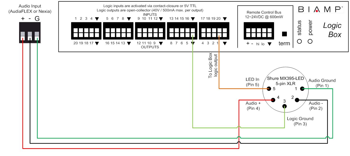
The audio conductors on the microphone will connect to the audio inputs on the Audia/Nexia like a typical microphone. The LED and Logic Ground conductor will connect to the Logic Box. The LED In conductor connects to a logic output, and the Logic Ground connects to any of the ground terminals on the Logic Box.
Each MX395-LED uses one logic input terminal on the Logic Box, which means that a maximum of 20 MX395-LED's can be connected to a single Logic Box. The diagram below shows a typical wiring scheme for a single MX395-LED:
LED control
The microphone's LED ring will light up green when there is less than 1V across pins 3 and 5 (i.e., logic output in the low state), and it will light up red when there is 5V across pins 3 and 5 (i.e., logic output in the high state).
Further reading
Once the device is physically connected to the Logic Box, you'll need to program it. See Logic Box Programming for more information.