Connecting a Shure MX392 or MX393 to a Logic Box
Goal
After completing the steps in this article, you will be able to connect a Shure MX392 or MX393 to a Biamp Logic Box. This will allow your Audia or Nexia configuration to control the LED on the MX392/393, and it will also allow the mic's mute switch to control functions within your Audia or Nexia configuration (like mic muting).
Note that Shure MX series microphones use phantom power to power its LED's. Therefore, no external power supply is required for this application.
Conductor colors
The Shure MX392/393 is a boundary microphone with a mute switch and a green LED. The MX392 comes with an unterminated cable. The MX393 comes with a cable that is pre-terminated to a 3-pin XLR, with 2 additional logic conductors available inside the XLR connector housing. The conductor color code for both mics is the same:
| Conductor Color | Function |
|---|---|
| Red | Audio + |
| Black | Audio - |
| Green | Audio/Logic Ground |
| Orange | LED In |
| White | Switch contact |
Wiring
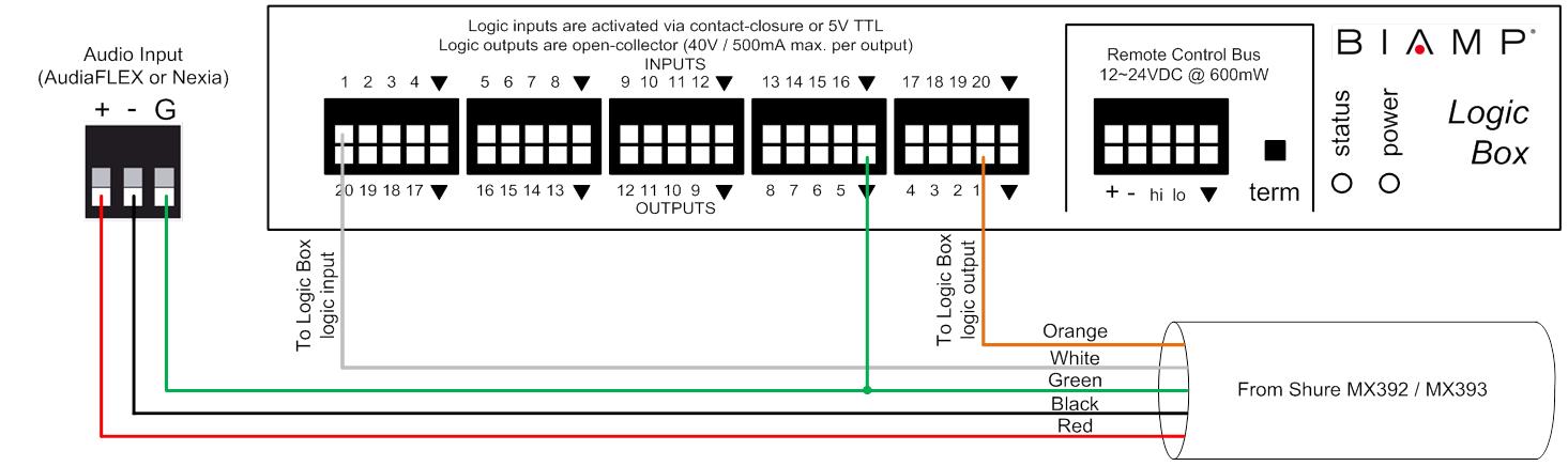
The audio conductors on the microphone will connect to the audio inputs on the Audia/Nexia like a typical microphone. The LED and switch conductors will connect to the Logic Box. The LED In (orange) conductor connects to a logic output, and the Switch Contact (white) connects to a logic input.
Each MX392/393 uses two I/O terminals on the Logic Box, meaning that a maximum of 10 MX392/393's can be connected to a single Logic Box. The diagram below shows a typical wiring scheme for a single MX392 or MX393:
DIP switches
DIP switch 3 should always be in the UP position to ensure that the mic is not locally muted when the mute switch is pressed.
If DIP switch 1 is in the UP position, the mute switch will behave like a toggle switch. If DIP switch 1 is in the DOWN position, the mute switch will behave like a momentary switch.
LED control
The LED will light up when there is less than 1V across the orange and green conductors (i.e., logic output in the low state). The LED will turn off when there is 5V across the orange and green conductors (i.e. logic output in the high state).
Further reading
Once the device is physically connected to the Logic Box, you'll need to program it. See Logic Box Programming for more information.