Wiring potentiometers to the Voltage Control Box
Wiring a generic potentiometer
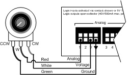
Wiring a potentiometer to a Voltage Control Box can be a bit confusing since it has three contact points. Not wiring it properly might cause the potentiometer to either work in reverse or not at all. Looking at the pot from the knob side with the contact points pointing at you, you will have the Low or CCW (Counter Clockwise) terminal on the left, the W (Wiper) terminal in the middle and the High or CW (Clockwise) terminal on the right. Connect the CCW terminal to Ground, the W terminal to the analog input and the CW terminal to the V terminal as shown in the diagram below.
The analog inputs on the Voltage Control Box support linear taper potentiometers with maximum resistance values between 5kΩ and 50kΩ. The Voltage Control Box's analog inputs can be calibrated to the resistance range of the potentiometer that is connected to it.

Wiring the RP-L1 or RP-L2
The Biamp RP-L1 and RP-L2 are wallplates with 25KΩ linear taper potentiometers for volume control. The RP-L1 has only one potentiometer while the RP-L2 has two. These potentiometers come prewired from the factory with pigtails for ease of installation. These pigtails are color coded green for Low or CCW (Counter Clockwise) terminal, red for W (Wiper) terminal and white for High or CW (Clockwise) terminal. Connect the CCW (green) wire to Ground, the W (red) wire to the analog input and the CW (white) wire to the V terminal as shown in the diagram below.
Please note that the RP-L1 and RP-L2 products have been discontinued as of Fall 2015.
Further reading
- All potentiometers that are connected to a Voltage Control Box must be calibrated to ensure proper operation. See How to calibrate a Voltage Control Box for more information.
- Once the device is physically connected to the Logic Box, you'll need to program it. See Logic Box Programming for more information.