Gain structure
This article describes establishing and maintaining good signal strength throughout the entire sound system.
Proper gain structure
Why is gain structure important?
Proper gain structure is important because it affects signal-to-noise performance and available headroom within a sound system. Every sound system has some inherent noise, whether it be self-generated by the internal electronics or induced into the signal path by external sources. Therefore, unnecessarily low gain settings can result in signal levels which are significantly closer to the noise floor, potentially causing a sound system to appear noisy. Conversely, excessive gain settings may cause the audio signal to overdrive the electronics, resulting in severe distortion due to clipping of the audio waveform. Besides being audibly undesirable, a distorted waveform can also cause damage to some system components, such as loudspeakers.
In addition to its influence on signal-to-noise and available headroom, gain structure can affect other aspects of sound system behavior. In particular, some audio components rely on signal strength as part of their normal operation. These components may not perform as expected if they receive signals that are lower, or higher, or even just different from what is anticipated. Examples of such components are: Auto Mixers, Duckers, Levelers, Comp/Limiters, Ambient Noise Compensators (ANC), and Acoustic Echo Cancellers (AEC).
Auto Mixer, Ducker, Leveler, and Comp / Limiter functions are triggered by input signals that exceed a specified threshold. With Levelers and Comp/Limiters, signal levels below threshold are not considered unusual (they simply are not affected by the component). However, Auto Mixers will not pass signals that are below threshold, and Duckers will not automatically attenuate program signal if the sensing input signal is below threshold. Furthermore, signals containing a large amount of background noise can falsely trigger these components, if the level is set too high and/or the threshold is set too low. It should also be noted that any real-time control of signal levels should not occur before these types of components. For example, control of individual Auto Mixer channels should not take place ahead of the Auto Mixer. Instead, the Auto Mixer Input Level controls (which are post-threshold) may be used for this purpose.
Ambient Noise Compensation (ANC) relies on a continuous and accurate model of the program signal level, to differentiate it from changes in the ambient noise level. So, real-time control of levels should not occur after this type of component. Acoustic Echo Cancellation (AEC) relies on a continuous and accurate model of the signal to be cancelled from the microphones. So, any real-time control of signal levels at the loudspeaker output should be duplicated for the AEC Reference. If these signals are different, a 2-channel ‘ganged’ Level control may be used.
What is proper gain structure?
Generally speaking, proper gain structure refers to establishing and maintaining good signal strength throughout the entire sound system. In most cases, this means that the relative volume of loudspeakers should ultimately be determined by adjustment of the power amplifiers after all prior system gain settings have been established. Other system outputs (such as recording feeds) may require lower levels, which should be established by selecting an appropriate reference level at the output itself. Other than real-time level control (as described previously), signal attenuation within the system should be avoided.
How do I set proper input gain?
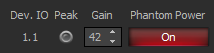
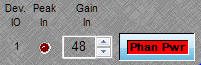
To establish proper gain structure, the primary element and first concern is input gain. Each system input provides adjustable Gain In or trim level, with an associated Peak indicator.
-
For best performance, increase the gain on a given input until the Peak indicator just begins to flash on normal signal content. The Peak indicator first comes on with 6dB of headroom remaining (before clipping occurs).
-
To provide additional headroom (that is, allowing for occasional louder input signals), it is recommended that the gain then be reduced by 12dB (two 6dB decrements).
Using meters
To monitor system levels, Peak Meters should be connected at strategic points in the signal path, including at the inputs and outputs. With gain settings as described above, input meters should indicate peak levels between 6dB and 12dB on normal signal content. This will provide a nominal level of approximately 0dBu, with good signal-to-noise performance and a safety margin of 12dB to 18dB of available headroom.
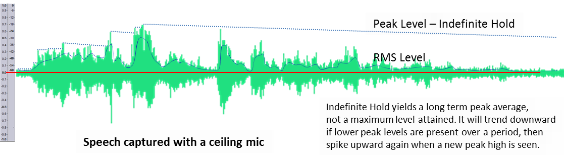
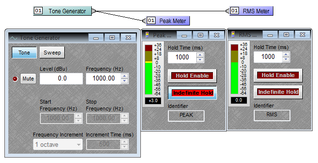
You can click "Hold Enable" and adjust the Hold Time on a meter to make it easier to see the average levels that are being hit. A Hold Enable time of 1000 ms (1 second) is useful on Peak Meters. "Indefinite Hold" averages the level over an indefinite (as long as it is running) period. It is not an infinite Peak Hold, it does not store the maximum value ever seen.
Peak Meters vs RMS Meters
Peak Level is a moving target, sometimes high, sometimes low, representing the instantaneous value of the audio level. A Peak Meter displays the instantaneous level of the signal as fast as it can. This is useful for metering highly transient signals, or for gauging the highest level of an audio signal regardless of how brief the peak is. Peak meters are important in digital systems since they allow you to see if a signal is approaching full-scale in the system.
An RMS meter has a slower response and displays a level that is averaged program level over time (300ms window). The result is that short-duration peak signals will not register as much on an RMS meter since there are corresponding lower levels aggregated in the averaging period, however the response of an RMS meter is generally considered to be closer to the response of the human ear.
RMS stands for Root Mean Square and it is representative of the average energy of the material. Peak indicates instantaneous spikes typically lasting only a fraction of a second. The difference between the RMS and peak levels indicates the crest factor of the material, the ratio of how far the peaks exceed the average.
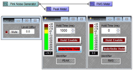
Note that sending the same signal to a Peak Meter and an RMS Meter will not result in an identical decibel reading on both meters. For instance, sending Pink Noise at 0dBu to a Peak Meter with Indefinite Hold will show peaks of up to +15 or higher (the crest factor of the pink noise) while the RMS meters will show values closer to 0dBu for the same time interval.
For a sine wave the crest factor is +3dB, this can be seen in the following capture.
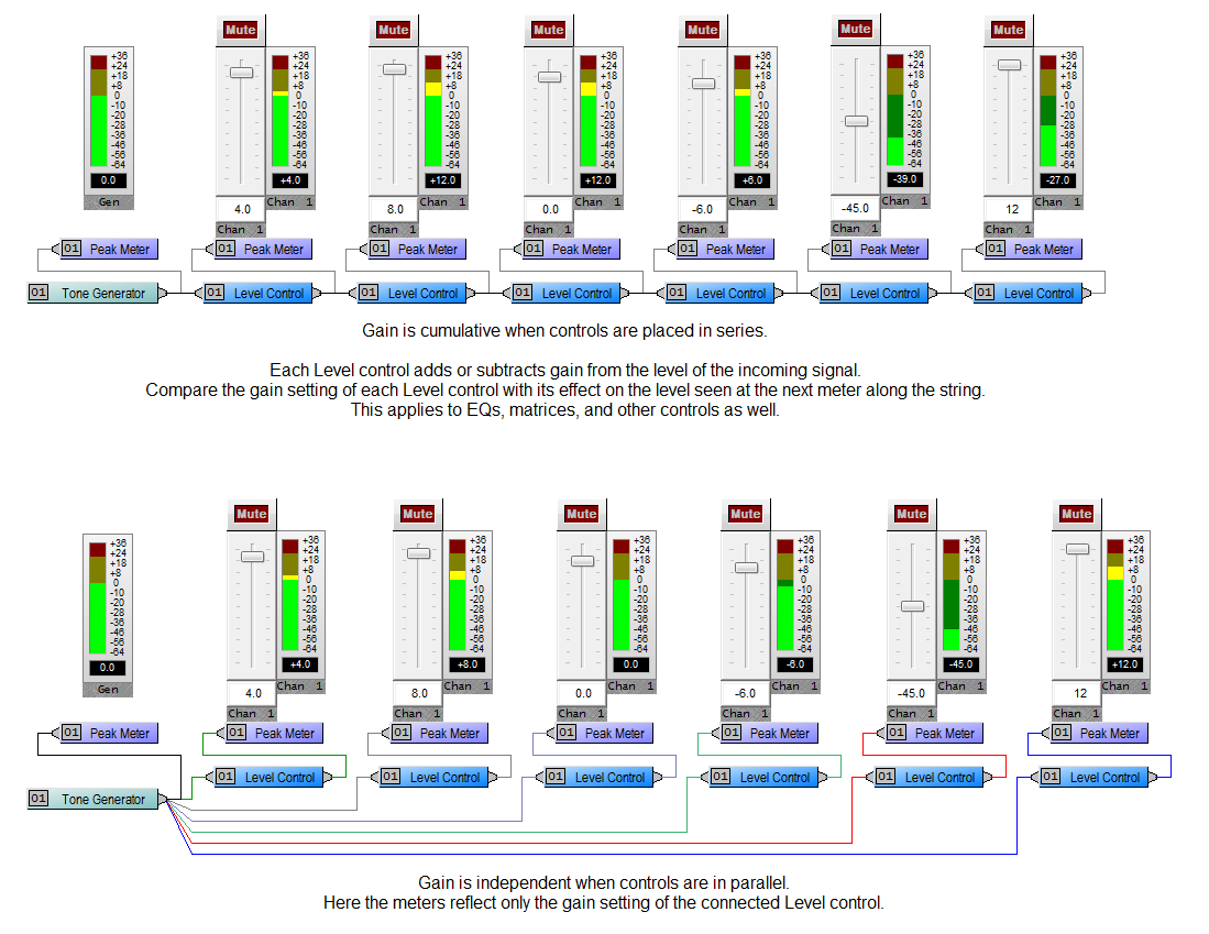
Adjusting faders
Many control components include internal level adjustment capabilities via level control (aka fader control). By default, these faders are at 0dB (unity gain) - meaning that the level passing through has neither been turned up or down. This is a very good setting for most applications, and does not necessarily need to be changed.
Faders can be used for real-time level control. Faders can be used to ‘mix’ multiple signals at differing levels to create a more comfortable listening experience.
Faders can also be used to compensate for gain reduction caused by other control components. This is called "make-up gain" and is frequently used to compensate for attenuation caused by Leveling, Comp/Limiting, etc. earlier in the signal path.
Floating Point DSP's allow fairly extreme gain staging without the danger of clipping distortion or the loss of data bits. As long as signal levels do not exceed the digital clipping point (0dB Full Scale) at the inputs or outputs of a discrete floating point DSP chip extremely high and low level signals can be tolerated without negative impact on audio quality. This DSP chip "edge" includes passing over AVB, CobraNet, NexLink, or Dante links or going through D/A converters. However, remember that some threshold-dependent system components do not function well without proper signal strength (as described previously).
Output gain
The final piece of the puzzle in proper gain structure is matching the output voltage of your system to the input sensitivity of your amplifier.
Every amplifier model may be different, even within a given product line from a single manufacturer. Always refer to the spec sheet for your amplifier and take a look at the input sensitivity for the amplifier! Once you have this information you can adjust the analog output level of the Biamp unit to match.
'Input Sensitivity' typically defines the RMS input voltage at which an amplifier will reach its full-rated power output. The clipping level or maximum level is going to be at a higher voltage. The margin between the 2 values indicates the headroom or crest factor of the amplifier and will vary between amplifiers and manufacturer.
Rated power on amplifiers may be expressed as peak or RMS power capability, it is important to know which is being used for the model under consideration. A 400-watt amplifier with an input sensitivity of 1.35Vrms should produce 400 watts when 1.35Vrms is supplied to it.
If an input voltage greater than the rated input sensitivity is applied the amplifier will produce a proportionally higher output level until it hits clipping, which is the highest output it can produce. An amplifier may not be stable at RMS input voltages higher than the rated input sensitivity, meaning it may go into thermal overload, become non-linear, or have other unexpected performance issues. Typically amps are stable as long as the program RMS level does not exceed the input sensitivity level, while momentary peaks can safely drive the amp to just below the maximum or clipping level.
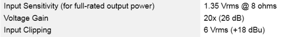
The specs below are for a common amplifier, you can see that the full power is reached at 1.35Vrms @ 8 ohms and the amplifier will be clipping at 6 Vrms (+18dBu). The voltage gain tells how much the amplifier is magnifying the voltage input, in this example a 1.35V input x 20 yields a 27.0V output.
Older amplifiers had an input circuits with an attenuation knob which would allow high input levels to be attenuated within the amplifier. It is less common to see this now, and many amplifiers need the input voltage scaled properly before it arrives at the input connectors.
Let's look at the output block of a Biamp unit. Here you can set the upper limit for the output voltage range from the unit, expressed in dBu. This is the maximum voltage the channel will deliver at its maximum possible amplitude (Full Scale output is reached when hitting red in the Biamp's peak meters). It is always recommended to place a Limiter block as the very last object before an output to an amplifier, set the threshold to +28.0 and the release time to 15ms to prevent accidental clipping in the D-A converter if the output is driven hard.
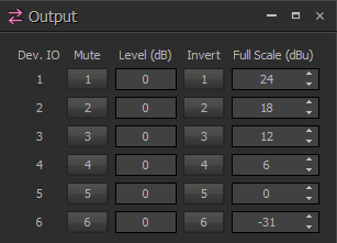
The Biamp Tesira, Audia and Nexia have preset dBu output levels of 0, 6, 12, 18, and 24 dBu. Tesira, Audia and Nexia also allows -31dBu for a "mic level" output. Check the "Enable Output Attenuation" box in the output block parameters to access these settings in Nexia and Audia
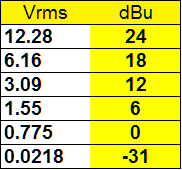
dBu can be converted to Vrms, it is just a different notation. A 6dBu change equals a doubling (2x) of voltage. Using a spreadsheet or calculator, you can calculate the values for fine tuning to the amp you are using with the formula
Vrms = 0.775*(10^(dBu/20))
dBu = 20*log10(Vrms/0.775)
The 6dBu increments on the Biamp will get you in the ballpark, you can then fine tune your amplifier's input by either attenuating the Level (dB) Out in the output block or by attenuating the input level on the amplifier. The bonus to doing it within the Biamp unit is that it can't be inadvertently changed after you have left the job site.
Plugging the second formula into a spreadsheet we can determine that the amplifier will reach full power at 8 ohms with the Biamp feeding it Full Scale input of 1.35 Vrms = 4.83 dBu. The amplifier doesn't clip until +18dBu, so any setting between +4.83 and +18 dBu would be allowable to acheive full output power without clipping the amplifier. The Biamp's default output level is +24dBu, so attenuating by -6dBu is necessary. If we don't attenuate the signal we will be clipping the amplifier's inputs and likely damaging the speakers.
Definitions
- Decibel
- The bel represents a ratio between two power quantities. A decibel (dB) is one tenth of a bel (B), i.e., 1B = 10dB, 1/10th B = 1dB. The human ear has a large dynamic range in audio perception. In listening tests the bel was used a reference unit for measuring a halving or doubling of perceived volume, a change of 10 decibels equal 1 bel. A sound that is loud enough to cause permanent hearing damage can be 1 trillion times louder than the quietest sound that the ear can hear (0 dBSPL). Such large measurement ranges are conveniently expressed in logarithmic units: the base-10 logarithm of one trillion (10^12) is 12, which is expressed as an audio level of 120 dB.
- dB, dBu, dBSPL
- A decibel (dB) is simply a logarithmic ratio of two numbers, it is a unitless value. Other decibel units (like dBu and dBSPL) are referenced to a specific value. For instance, dBu is a decibel measurement of voltage, and is referenced to 0.775 volts RMS. Therefore, 0dBu = 0.775 volts RMS. Every other dBu value is measuring how far you are (on a logarithmic scale) from 0.775V. Sound pressure level (SPL) is measured on a decibel scale using dBSPL, which is referenced to 20 micropascals of pressure. Therefore, 0dBSPL = 20 micropascals, which is approximately the quietest sound that the human ear can perceive. Other values of dBSPL are measuring how far you are (on a logarithmic scale) from 20 micropascals.
- SNR (Signal to Noise Ratio)
- SNR is expressed as a ratio of between the reference level of a piece of audio equipment (on pro audio gear, usually referenced to +4dBu) and its noise floor.
- Dynamic Range
- Dynamic range refers to the maximum possible range a system can reproduce, measured from the noise floor to the onset of distortion due to levels exceeding the capabilities of the system components.
- Noise Floor
- Noise floor refers to the lowest usable level available in an audio system before the electronic noise (hum, hiss, etc.) of the system becomes the dominant characteristic. Ambient noise being picked up by microphones can also define your operational noise floor.
- Headroom
- Headroom refers to the amount of usable operating voltage range above the average program level for a signal, prior to clipping. If a signal plays along at 0dBu (0.775 volts RMS) but the circuits do not distort until +24dBu, we have about 24dB of headroom. If the circuit overloads (clips or distorts) at +7dBu then we have 7dB of headroom. Headroom is important because of transients, louder spikes in program material, which need to pass through the system intact. For spoken word events 12dBu of headroom may be fine, for musical performances 20 to 24dBu may be needed. Different audio devices will have different maximum operating voltages, the lowest of these defines the headroom for your signal path.
- Transients
- Transients are defined as a short-duration, high-amplitude (loud) event. Examples of transients can include a yell, a sneeze, a whistle, a snare drum, or a clap. Compressors and limiters are useful tools in protecting your system from damage from transients.
- Threshold
- In audio systems a threshold refers to a preset or user-defined level which a signal must pass to invoke a response. For instance, in a compressor, if the threshold is set to +4dBu then any audio signal with a maximum amplitude of less than +4dBu will pass by unaffected while any signal with an amplitude greater than +4dBu will trigger compression whenever it exceeds threshold.
- Gain
- Gain refers to the increase in level to an audio signal in a system. It is commonly used in reference to the adjustment made to the microphone preamp stage where the low voltage microphone output signal (approximately -35dBu) is amplified to line level (0dBu). An addition in level can be applied anywhere in the system and is still called gain.
- Attenuation
- Turning down a level is referred to as attenuating or attenuation of the level.
- Clipping
- The clipping point refers to the level where an audio system is driven into distortion. In analog systems this is seen through the onset of squared waves which occur as the peak voltages through the system exceeds the ability of the components to pass the waveforms unchanged - the excess voltage is unable to pass by and is "squished" down to the maximum level, the resulting waveform has a "square" top as a result of "clipping" the electronic ceiling. In digital systems clipping takes the form of overwhelming the dynamic range of the digital algorithms, resulting in digital "hash" or noise.
- Distortion
- Distortion refers to any disruption of the original audio signal which results in a corruption of the signal integrity. While many guitar players like distortion, users of distributed audio systems tend to find it annoying.
- Unity
- Unity is often used in reference to faders, to have the fader at unity means to have it at 0dBu, where it is neither boosting nor attenuating the signal. Unity can also be used to describe the signal level. If someone refers to a signal at unity they typically mean it is at 0dBu, although truly a signal at unity is just a signal which is unchanged in level with regard to a reference.