Logic Delay applications
In Audia and Nexia, you can add a lot of automatic functionality or external control using logic. In some cases, we might need to prevent false triggering or modify the duration of a logic pulse. The Logic Delay block can help if we understand how it works.
Logic Delay block
Contrary to an audio delay where a signal is “recorded” and then “played” back (i.e we always get the input signal at the output), the Logic Delay is more like a buffer. It will stop logic signal propagation for a certain amount of time after which, if the signal is still present at the input, it will propagate to the output. The Logic Delay block allows for setting an On delay and an Off delay so either (or both) sides of a logic signal can be buffered.
- On Delay
- When an On Delay is set in the Logic Delay block, this means that the input logic signal must remain high (or ON) for that period of time, uninterrupted, before the Logic Delay will allow that logic signal to pass. It is functionally similar to the threshold in audio blocks, a signal which meets or exceed the threshold value opens the gate.
- Off Delay
- When an Off Delay is set in the Logic Delay block, this means that the input logic signal must remain low (or OFF) for the defined period of time, uninterrupted, before the Logic Delay will allow that logic low signal to pass. The effect is the same as if you were to simply extend the duration of any logic high passing through the block by the Logic OFF Delay time.
Logic Delay applications
Please note that all of the following examples assume that a HIGH logic signal is the trigger signal. The same functionality can be achieved for a LOW logic trigger by setting the delay time on the opposite delay field.
To prevent false triggering or as a de-bouncer
Using a short delay time, usually below 100ms, prevents false triggers from passing through. Shorter signals than the On Delay time will be ignored.
To increase a logic pulse width
By delaying the Off time, we can increase the pulse width to make fast pulses easier to read. The resulting pulse will be as long as the original pulse plus the Off delay.
To decrease a logic pulse width
Regardless of how long the logic signal stays on, the resulting signal will turn off creating a short pulse. The input logic signal must stay on for at least as long as the On Delay time.
To create a sequence of events
Each event will be triggered after the previous On delay time has elapsed. Logic signal needs to remain on while the sequence is executing. As an option, the last event could be used to reset the trigger.
To create a self-resetting switches
Once the action is triggered from a preset, the Flip-Flop gate will reset itself after the On delay time has elapsed. (To make this work with the opposite signal you’ll need a couple of NOT gates).
To create a momentary latching pulse
The Flip-Flop gate responds to the LGSTATE command via serial or IP control. Use this circuit to create a "Mute" command which will set mute on after the first command is sent, and mute off after the command is resent.
Use the command “SET 1 LGSTATE 12 1 1” to set the upper Flip-Flop gate to True. (Where 12 represents the Instance ID of the upper Flip-Flop gate.)
Use a Logic Delay On setting of 100ms to delay the logic pulse, allowing it to pass and reset the upper Flip-Flop to False after 100ms.
The initial True state of the upper Flip-Flop gate triggers the lower Flip-Flop gate to True, engaging the Mute. The lower Flip-Flop gate will remain True until the next time the upper Flip-Flop gate is toggled to True.
The same effect can be achieved using a preset to set the upper Flip-Flop gate to True.
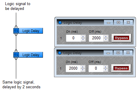
To delay a logic signal
To make the Logic Delay block work more like an audio delay (where any incoming signal is delayed and sent out later), we need to use them in pairs. The diagram below will delay logic HIGH pulses. To delay LOW pulses, swap the Logic Delays so that the On delay happens first.

