Room Combiner block
The Room Combiner DSP block found in Audia and Nexia is a powerful, easy-to-use tool for implementing room combining applications. The room combiner allows up to 32 rooms to be combined in almost any number of geometric layouts. Rooms can then be combined and separated using a variety of methods: external contact closure or push button, presets, control system commands, or via mouse and the Audia and / or Nexia software.
Creating a Room Combiner block
To utilize the Room Combiner in an Audia or Nexia layout, first select it from the Object Tool Bar located under the Mixer Object.
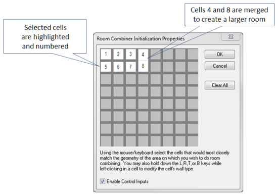
Next, click in the layout area. The Room Combiner Initialization Properties will appear with 64 cells placed into 8 columns and 8 rows. Using your mouse, click on each cell (32 maximum may be selected at a time) to select the room geometry of your particular room combining application. By right clicking, multiple cells can be merged to create larger and odd shaped rooms. Or cells can be isolated from one another to create rooms that may not be included in a particular room combining scenario.
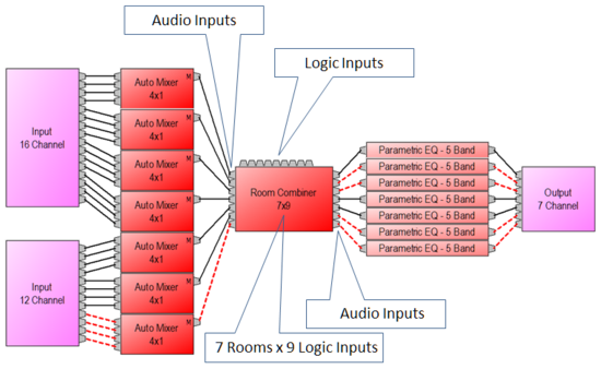
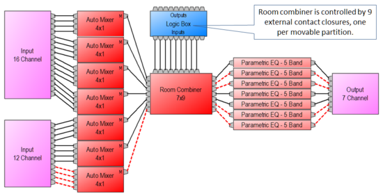
After selecting your room combiner layout, click OK and the DSP block will be placed into the Audia or Nexia layout. The block will have one input node for each room, one output node for each room, and one logic input node for each moveable partition. Wire inputs to the room combiner just as you would any other DSP block. Inputs can come directly from Audia or Nexia input blocks or from any other DSP block. When wiring directly from Auto Mixer main outputs to Room Combiner inputs, auto mixer ATS (Adaptive Threshold Sensing) and NOM (Number of Open Mics) data is automatically combined when the appropriate rooms are combined. Room Combiner outputs can then be wired to any sort of DSP block desired and routed to the appropriate output channel.
Controlling the Room Combiner block
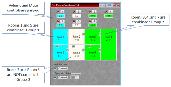
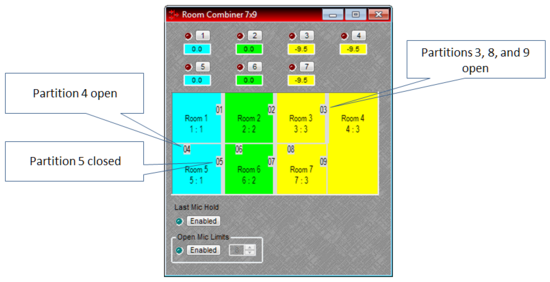
Double-clicking the Room Combiner block will open its control dialog. Here you will see the layout of your rooms as well as a volume and mute control for each room. Each room will be numbered sequentially. Custom names can be given to each room simply by clicking on the room number and typing in a new name. Each room also has a numbering scheme (1:1, 2:1, 3:1, etc.) that represents the room number followed by a group number.
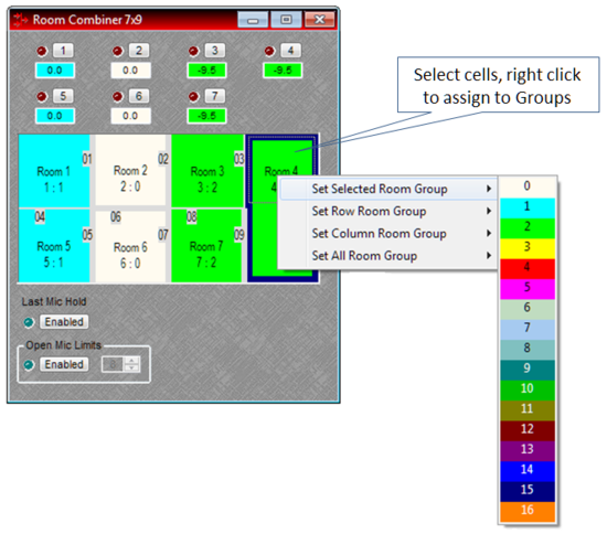
Rooms can be combined by highlighting the desired rooms with your mouse, right clicking, and selecting a group 1-16. The selected rooms will become the same color. The volume and mute controls for the combined rooms will also become the same color and their control will be ganged. When rooms with different volume levels are combined, all combined room volume levels will be set to the level of the room with the lowest setting. If a room is muted, any other room that combines with it will become muted as well. This method of combining will work for adjacent and non-adjacent rooms.
Room combiner wall states can also be opened and closed via the mouse. Simply mouse over the partition, the pointer will change shape to indicate correct positioning, and then click. The partition line will turn thinner to denote the wall being open. The combined rooms will turn the same color indicating the rooms are now combined. Clicking a second time will close the wall. The partition line will turn thick, indicating the wall is closed and the rooms will now turn white indicating they are separate and not combined.
Presets
Room combinations created in this method can be saved to presets. The appropriate preset can then be recalled when rooms need to be combined or separated.
RS-232 / Telnet
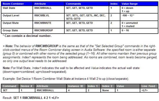
Room combining can also be controlled through RS-232 / Telnet strings (see Audia or Nexia RS-232 / Telnet Control Protocol document. Simply send strings to place each room into a desired group.
Partitions can be opened and closed through RS-232 / Telnet strings as well (see Audia or Nexia RS-232 / Telnet Control Protocol document.) Simply send strings to open and close each partition within the room combiner block to automate room combining with 3rd party controls.
Logic inputs
An alternate method of controlling the room combiner is through the use of logic inputs. The Room Combiner has one logic input per moveable partition. Each partition has a number that corresponds to the logic inputs numbered 1-x, left to right on the top of the block. Logic inputs allow external contact closures to signal a moveable partition within the block to open or close. When a contact is closed, the partition will open. When a contact opens, the partition will close. When a partition opens, the adjacent rooms combine. When the partition closes, the adjacent rooms separate.
Room Combiner logic inputs can be controlled by the Logic Box in conjunction with external switches or by the Select-8 or Volume/Select-8 remote control panel.
Logic gates can also be used to set conditional behavior for the logic circuits.
Automixer combining
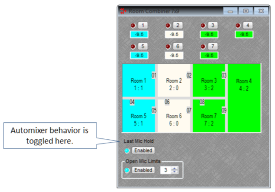
If Auto Mixer blocks are used immediately preceding the Room Combiner (with no other blocks between them), it is possible to dynamically combine the Auto Mixers when their rooms are combined. The settings applied in the Room Combiner will be passed to all Auto Mixers in the Group. In our examples, the Auto Mixers in Room 1 and 5 will be merged into one Auto Mixer with Last Mic Hold enabled and an Open Mic Limit of 3. The Auto Mixers in Room 3, 4, and 7 will be merged into another Auto Mixer with Last Mic Hold enabled and an Open Mic Limit of 3.


