Progress indication - System busy
This article covers how process progress indication works on Biamp Control controllers. This includes how to modify the appearance as well as how to set progress automation on both Control keypad device as well as touch panel user interfaces using Biamp Project Designer.
Concept overview
The design philosophy behind progress indication on Biamp Control devices can be described as: "When it's blinking it's thinking, when it's steady it's ready" In other words, a keypad button LED or a display panel user interface button indicates the system is processing by using either a blinking indicator or a graphical overlay.
Processing is defined as sending out sequences and waiting until the connected devices are done handling the received sequences. By way of example, a Power ON command and an automatic follow-up command to change to a specific source such as HDMI 2.
How it works
Progress indication time lengths are taken from the timing found in device drivers. Timing is added to a project in the Systems view of Biamp Project Designer. Every command or sequence must have a time so the controller knows when the device at the other end of the wires is ready to accept additional commands. For example, if a Power ON command is sent to a device immediately followed by a Source command, the device will not have time to finish its power on cycle before the second signal arrives. This will result in the Source command not registering. A user would then have to press the button a second time to resend the commands again.
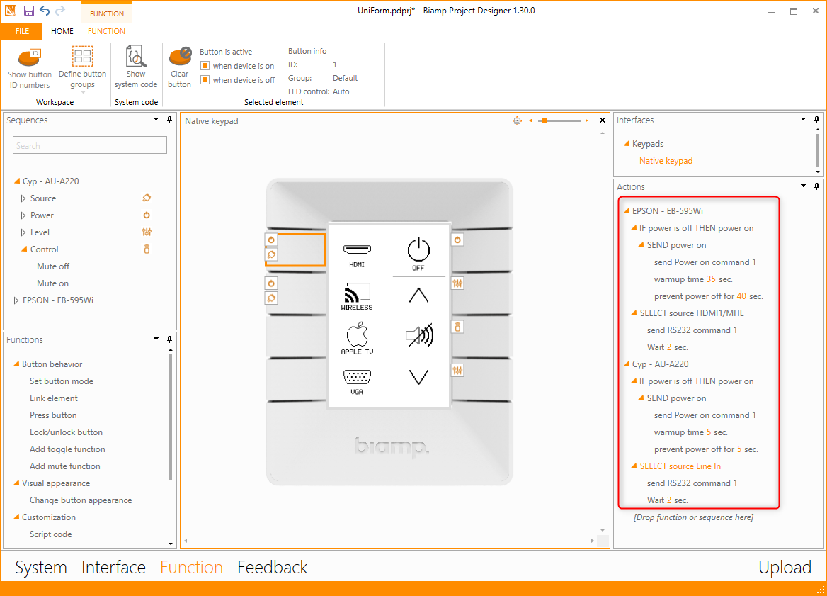
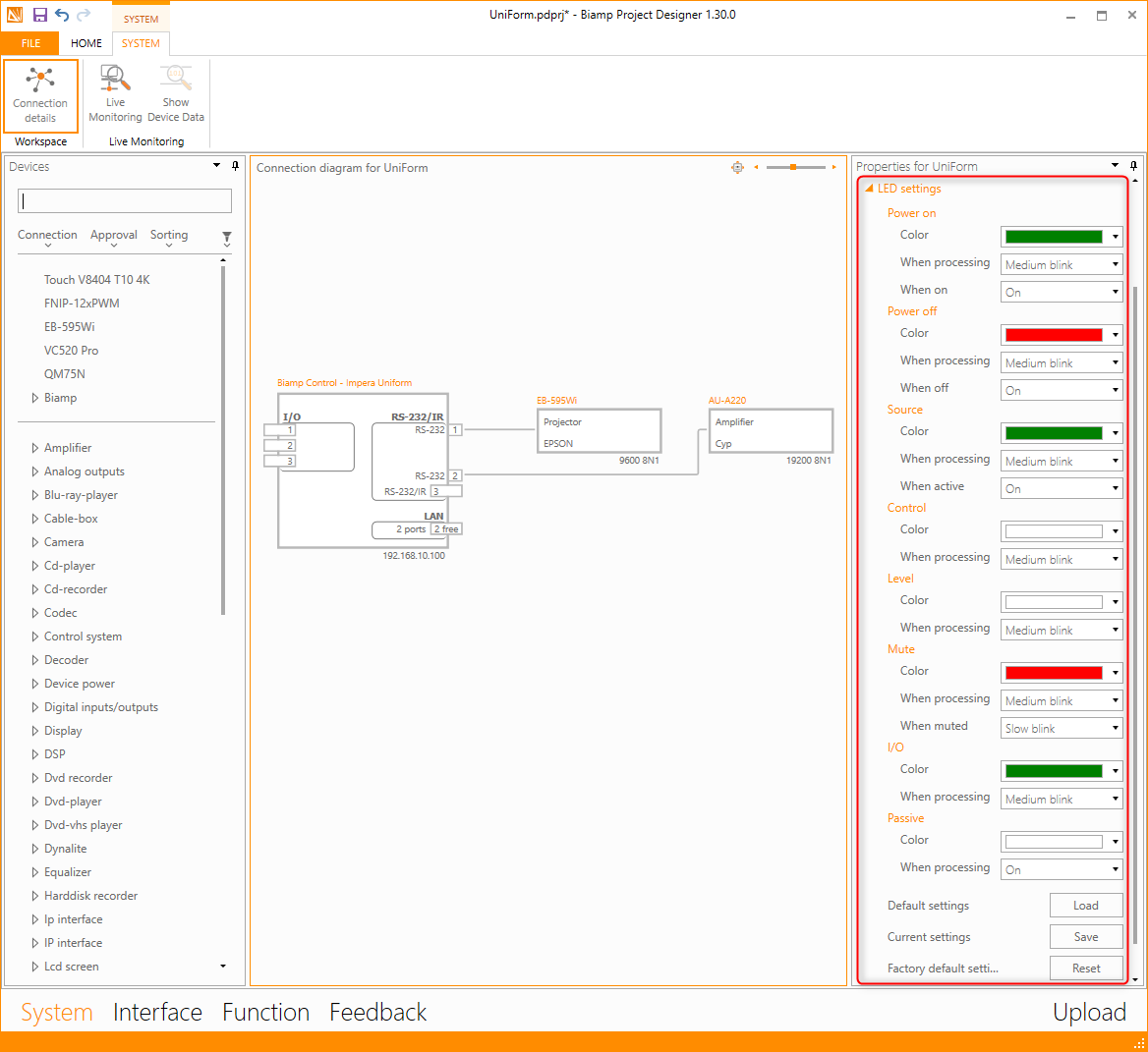
The Biamp Project Designer screenshot below depicts an example controller with a projector and an amplifier connected. These peripherals turn on and change the source when the top left hardware button on the controller device is first pushed. The timing data is noted in the orange text on the "Actions" panel found on the right side of the screen (circled in red). As previously mentioned, these timing settings are taken from the device drivers.
Processing indicator
In this example, the button's LED will blink for a total of 37 seconds following a button press. This is because the projector takes 35 seconds to warm up and then the source change takes 2 seconds. The amplifier will also be ready when the processing indication finishes since its power ON cycle and source changes run concurrently and take just 7 seconds.
Additional buttons cannot be utilized for these devices while the controller is processing. This is a button interlock function. However, the controller can send command signals to a third device not related to the button pressed.
Busy Indicator
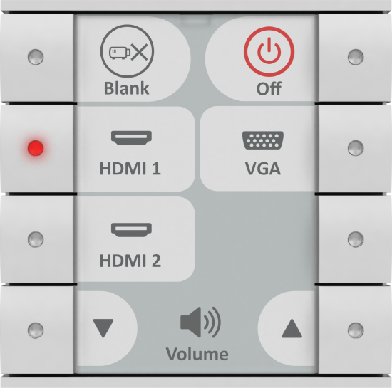
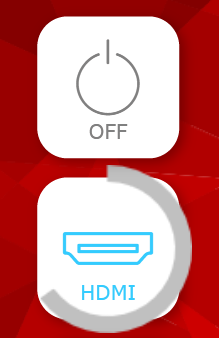
Pressing a hardware button while the system is busy processing a command or command sequence causes the button's LED to blink rapidly. Doing so on a touch display brings up a busy indication overlay on the user interface (UI) button. See the example below.
Processing finished
On a keypad, when the sequences have been sent and the waiting period is over, the blinking stops and the LED turns into a solid color.
Keypad hardware button options
Indicator color changes and blinking frequency automation can be customized on most keypad controllers. Note that the Echo, Echo Plus and Oscar controllers have red LEDs and cannot change colors.
Changing the settings
To change the indicator automation, go to the System tab in the top ribbon, select the controller, then select the LED settings in the Properties panel for the device (outlined in red in the screenshot below.)
- The Power color can be set to one of the 7 available colors
- The LED indicator signal for busy and done can be set here.
- Addition modes may be set here as well, including setting passive buttons to display a color.
- Note: The Uniform controller is set to white as default when passive.
You can save your settings as the default for your controllers or reset them to factory defaults in this menu.
Graphical user interface options
Rather than LED lights, touch panels user interfaces represent the progress by showing an overlay above the pressed button. This uses the same automation processes as the keypad LEDs.
Changing the Progress settings
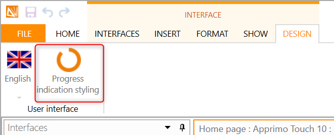
Select the Design option under the Interface tab in the top ribbon, then press "Progress indication styling"
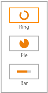
- Styling options for the progress overlay will now be visible. The first options the Ring, a Pie or a Bar shapes as shown here:
- The next available selection is the button overlay color (background color) and the color of the shape.
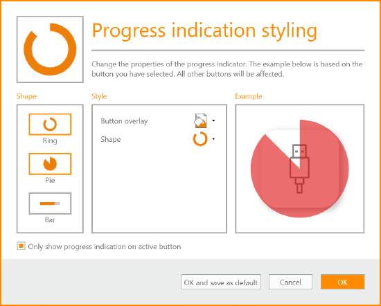
Tip: Transparent colors are a good design choice.
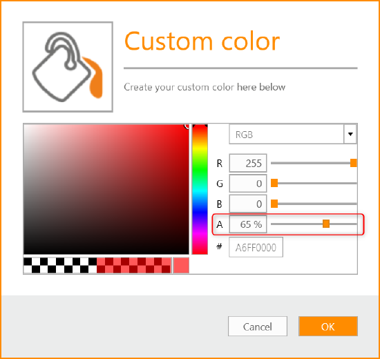
- Transparency can be selected under "more colors" in the dropdown color picker.
- To adjust the level of transparency, adjust the Alpha channel marked "A" (circled in red rectangle below).
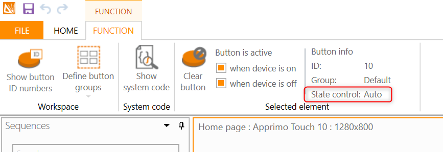
Auto or manual state control
The button state for keypad and UI buttons can be seen in Project designer under the top ribbon's Function tab while the button is being pushed. The state control setting of Auto or Manual is visible here. This setting is changed using the "Change button appearance" function. Manual enables custom settings for LEDs and graphical user interfaces.