Cambridge Qt emitter cable requirements and testing
For a new Qt X and legacy QtPro sound masking system to function properly, it is imperative that all 8-conductor, UTP category cabling be tested for continuity prior to installation. Sound masking emitters will not function properly if they've been connected by cabling that has been terminated incorrectly.
The majority of issues encountered during installation can be traced back to cabling that is either defective, or incorrectly terminated.
Troubleshooting Standard Emitters
Troubleshooting Active Emitters
An investment of time spent on proper cable testing at the start of a Qt X installation will save time later in the process. Troubleshooting any cabling that has not been tested, and is now triggering system faults, will most likely require more time to resolve than if the cabling had been tested initially.
Emitter cable requirements
- 8 conductor - 24 AWG Solid - UTP
- Category cable must be one of the following: Cat 3, Cat 5, Cat 5e, Cat 6, Cat 7
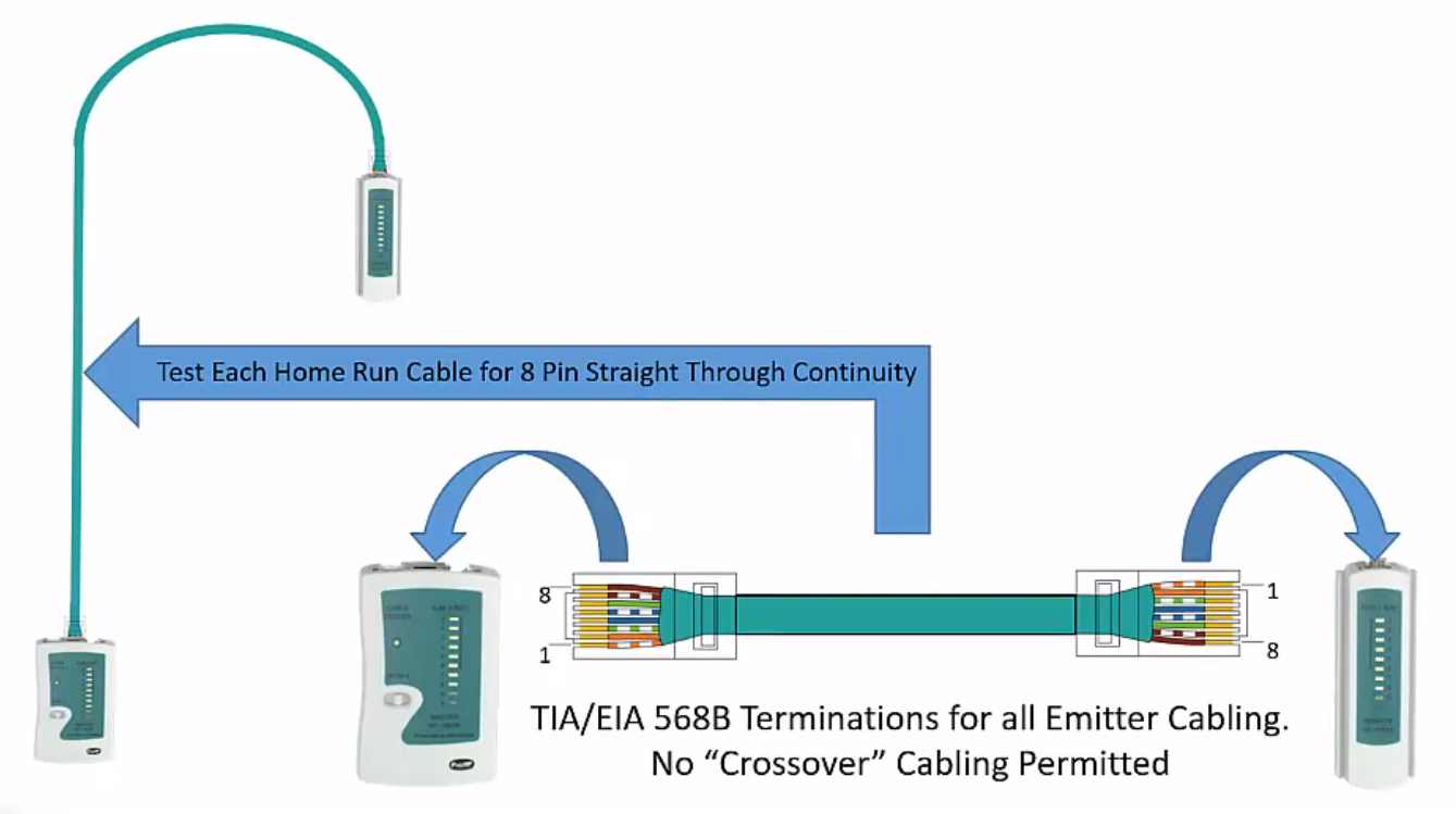
- Cables must be terminated using TIA/EIA 568B termination standard
- Cabling installed in plenum ceiling spaces should be plenum rated, to comply with building codes related to fire safety
Cable testing
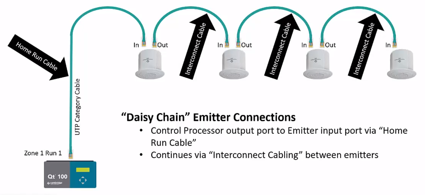
The testing of cables should be completed using a sequential cable tester, and the best place to begin this testing is with the home run cable that is used to make the connection from a zone/run on the Qt control processor to the first sound masking emitter in that zone.
After testing the home run cable, and verifying continuity and proper termination, it is best practice to then test each interconnect cable used in the emitter daisy chain. Prior to connecting an interconnect cable to the next emitter in the chain, test the cable with the continuity tester. If the cable test verifies continuity, then connect the cable from the Output jack of the previous emitter in the chain to the Input jack of the next emitter in the chain. Throughout the installation process, continue to follow this practice of testing cables before connecting them to emitters.
Troubleshooting tips
Troubleshooting should be done with the following elements in place:
- a single cable run connected to the zone output of the controller
- the sound masking level of the zone set to an audible level
- verification that the home run cable has been tested with an 8 pin continuity tester
Next, use the following instructions to troubleshoot the emitters & cable run:
-
Verify that the first four emitters are working properly when signal is applied to the home run cable/first four emitters. Verify that the correct connections have been made from Output to Input jack on the emitters in the daisy chain.
Never plug these cables in reverse to make a cable run of emitters operable, as it will further complicate troubleshooting further down the cable run.
(Emitters use four sequencing audio channels which are present on each Category cable in the run) -
Add four additional emitters to the cable run, making sure that Input and Output jacks are not swapped. Verify that an audible sound masking signal is present at each emitter.
-
Continue this process in groups of four emitters, until all emitters on this run are successfully working and connected properly, observing the Input and Output labels on the rear of the emitter. After the entire run of emitters has been confirmed to be operable, and there are no faults displayed on the controller, repeat steps 1 thru 3 for the next cable run on the Output of the controller.
-
Should an emitter not operate (no sound present) as you work toward the end of the cable run, stop there and work in reverse on the cable run toward the controller. Begin with the cable connected to the Input at the inoperable emitter, and then test each of the previous four cables for proper continuity using the tester. (See note below regarding the testing of cables and energized Active emitter lines)
-
Once the faulty cable of the four is identified, re-terminated, or replaced, then begin working once again toward the end of the cable run in groups of four additional emitters. Ensure that each emitter's cable is connected to the Input jack toward the controller and Output jack toward the end of the cable run as troubleshooting continues.
-
Repeat steps 4 and 5 for any emitter found to be non-operable, until the end of the run is reached, with all emitters connected properly and emitting an audible sound masking signal. The cable run is now sequencing all four audio channels throughout the emitter run to the last emitter.
If any input and output jacks are swapped throughout a cable run, that will prohibit success with this troubleshooting technique.
Each emitter must be connected from Output jack to Input jack.
Each cable must pass all eight conductors from the controller through to the end of the cable run.
A loss of connectivity in any one of these 8 conductors will result in one of the next four emitters becoming inoperable.
*Note - When testing cables with an 8 pin continuity tester, make sure that both ends of the cable are disconnected while testing. Active emitter systems contain voltage (powering the on-board amplifier) which may damage the continuity tester when the circuit is energized.