Troubleshooting Standard Adjustable Emitter Circuits - The First Four
Summary
This article will provide guidance for a basic understanding of how to troubleshoot sound masking signals in Standard Adjustable Emitter circuits.
With this how-to information, you will be able to identify the common issues found with standard adjustable emitter installation and how to determine the source of the problem quickly and easily.
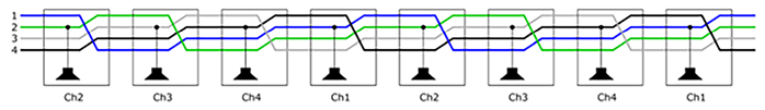
Output X – Run A = Channels 2,3,4,1,2,3,4,1,2,3 etc.
Output X – Run B = Channels 4,1,2,3,4,1,2,3,4,1 etc.

The foundation
The functionality of a standard adjustable emitter sound masking circuit may be determined by the first four emitters of that circuit. To build a complete circuit, ensure that each of the first four emitters in the circuit run are operating correctly:
1. Power up your Qt X300/600 controller and make sure there are no system faults shown on the front panel display.
2. From the front panel of the controller, increase the volume level of a chosen output/zone to an audible level.
3. Connect your home run cable to your controller's selected output/zone.
4. Starting at the 1st position emitter in your circuit, connect the home run cable to the “Input” RJ45 jack of the emitter. Listen to the emitter to make sure the masking signal is audible before connecting the next emitter in the daisy chain.
5. Once you have confirmed the 1st position emitter is working, the 2nd, 3rd and 4th position emitters can be connected correctly in order using the "Input" and "Output" RJ45 jacks on the emitters. You will need to listen to each emitter prior to moving to the next emitter in the circuit to ensure each emitter is audible and of the same level of intensity. This exercise will confirm each emitter channel, A,B,C &D, are all working correctly.

Note: Due to the channel sequencing of sound masking channels within the emitter, It is important that the emitters are connected correctly using the "input" and "output" RJ45 jacks on the emitter. If emitters are corrected incorrectly, the troubleshooting exercise will result in incorrect information.
Understand the possibilities
If you determine that you have an emitter that is not functioning, listed below are some possible failure points to troubleshoot the process. For this example, the emitter in the 2nd position is determined to be a non-working emitter:
1. The control processor could have a bad channel. (not typical)
2. The home run able could be improperly terminated or damaged. (very possible)
3. A bad emitter interconnect cable. (possible)
4. The second emitter could be bad. (not typical)
5. Compromised input/output pins in the RJ-45 connections of the previous emitter. (possible)
Multiple Failures (emitter, interconnect cable, home run cable, controller.) (very uncommon)

Troubleshooting
When troubleshooting a Standard Adjustable Emitter-based circuit start with the most likely items of fault. Work through the list eliminating each possibility until you arrive at a successful outcome. The list of items by probability is as follows:
1. Cables, home run cables and Interconnect cables.
2. Emitters.
3. Control processor.
Note: It is very common that the home run cable is the issue within the first four emitters simply because it is typically a field-terminated cable. This is an efficient place to begin the troubleshooting process.
In the following example, the emitter in 2nd position is not functioning. The following is the recommended method to begin troubleshooting the circuit.
Step 1 - Perform a home run cable test.
- Using a cable tester -Test all four channels (8 conductors) for continuity.
- Make sure there are no pin swaps within the termination.
Once the home run cable has been tested and confirmed as operational, check it off the list and continue troubleshooting.

Step 2 - Perform an interconnect cable test.
Test the interconnect cable between the 1st and 2nd position emitters. Look for two separate confirmations during the test.
- Using a cable tester -Test all four channels (8 conductors) for continuity.
- Make sure there are no pin swaps within the termination.
Once the first interconnect cable has been tested and confirmed as operational, check it off the list and continue troubleshooting.

Step 3 - Perform an emitter swap test.
Once both the home run and interconnect cables are confirmed as operational, if the issue persists, check the emitters.
The way to determine if the issue is the emitter, switch its position in the run with a functional emitter.
In this example, after switching the 3rd and 2nd emitter positions in the run, the problem moved along with the emitter and it is likely that the emitter is the issue.
If however, the problem had remained at the same emitter position, after the emitter positions are swapped, the emitter would likely not be the source of the issue and further troubleshooting would be required.

Step 4 - Perform an emitter swap test - previous emitter
Due to the vertical orientation of the emitter connections, It is possible to deal with compromised input/output pins in the RJ-45 jacks of the first emitter. Test this by switching its position with a functional emitter in the run.
As before, if the issues follow the non-functional emitter, it is assumed that the emitter is inoperable and should be replaced.
Switching the non-working emitter with the emitter proceeding it in the circuit tests the output connections of the emitter which was previously in the first position. If the problem moves further down the circuit to the emitter in the 3rd position, carefully examine the output connector of the emitter which was moved to the 2nd position in the circuit. If the problem remains in the 2nd position after this swap, there is likely another issue altogether causing the second emitter to be non-functional.
Once the emitters and their positions have been tested and can be assumed to be operational, check them off the list and continue troubleshooting.

Step 5 - The Controller
It is not typical for a sound masking control module to malfunction as it relates to the emitter circuits. If the controller is determined to be defective please contact Technical Support to confirm, and determine a replacement path.
Note: If you have a front panel temperature notification ie. "Device exceeded maximum temperature", this is typically still a circuit issue involving cables and/or emitters. You will need to follow these steps:
- Unplug the circuit from the controller
- Restart the controller
- Once the controller reboots, make sure the temperature fault has cleared.
- Begin at step 1 of the troubleshooting process to determine the issue.
Conclusion
This article covered how to troubleshoot the first four emitters of a Standard Adjustable Emitter circuit for proper functionality. This is an exercise that allows installers to set themselves up for success when installing circuits with multiple standard adjustable emitters. If the first four emitters in a circuit are working correctly, this will typically determine that the associated processor, the home run cable, the connection cables, and the emitters are functioning properly and all four channels of sound masking can now be duplicated to the additional emitters that will be added to the rest of the circuit.
What is not covered in this article is the connection cables and emitters in the circuit beyond the first four, and what effect those connections and emitters may have on the operation of the first four emitters and the processor.
Further Reading