Qt X Configuration through web interface
Overview
This article covers a generalized workflow for configuring, commissioning, and updating a Qt X sound masking system using a controller's onboard web interface. This includes:
- Configuring a new Qt X device
- Adding devices to a new or existing system
- Assigning zones
- Configuring audio inputs
- Programming logic I/O
- Tuning outputs
- Scheduling a system soft start
- Updating firmware
- Applying security settings to a system.
- All settings and features available through the software
For additional features not available in the web interface, please check out the Qt X Software.
Functions not available in the Web UI
Use the Qt X system management software for:
- Bulk firmware updates
- Importing and utilizing floor layout images when creating floor plans
- Saving and uploading .qdd system files
- Managing custom certificates
- Managing 802.1X
Designing a Qt X system
This article does not cover the design or installation of a Qt X system from layout and coverage. However, it does outline setting up zones and loading a configuration to a controller or group of controllers.
For more complex systems consisting of larger spaces and floors or to address other complexities, contact Biamp's CSM design team to assist with generating a layout and materials list. The design team can be reached using this link to request assistance with a design quote.
Getting started
Factory configuration
All Qt X hardware ships with a default 1:1 zone configuration loaded. This is also the default configuration that loads following a factory reset procedure.
The configuration may be cleared using the System Settings page under the System Info tab.
The factory configuration can be used as a starting point and edited as required within the configuration pages. These changes may then be sent to the system and adjusted in real time on the System Settings pages.
Note: The System Settings option will not be available in the web UI if the configuration has been cleared, In other words, if the system is unconfigured). A new configuration must be loaded to restore the Systems Setting option.
Connecting to the web interface
The web interface connects to a single device on the network. However, once connected, the Control interface (or AVB interface if the device is in Single Cable Mode) provides access to all configured devices in the Qt X system as well as any unconfigured devices on the same network.
IP Address and hostname
In your web browser, enter the device's IP address or hostname into the browser bar to navigate to the Qt X's secure HTTPS web interface. If the device is part of a protected system, you will be asked to enter user credentials to log into the system.
- The IP address of QT X devices can be found on the front LCD panel.
- The default hostname is the device's Qt X model followed by the device's serial number. For example, QtX300-XXXXXXXX.
Network settings
To configure the network settings, go to the Device Settings page and select the Network Settings tab. Here, changes can be made to the device hostname as well as adding primary and secondary DNS servers if necessary. Additionally, the cable mode can be set to Single and Dual Cable Modes. Note that Qt X controllers default to Single Cable Mode. Single Cable allows for setting a static IP address, subnet mask, and gateway for the Control network.
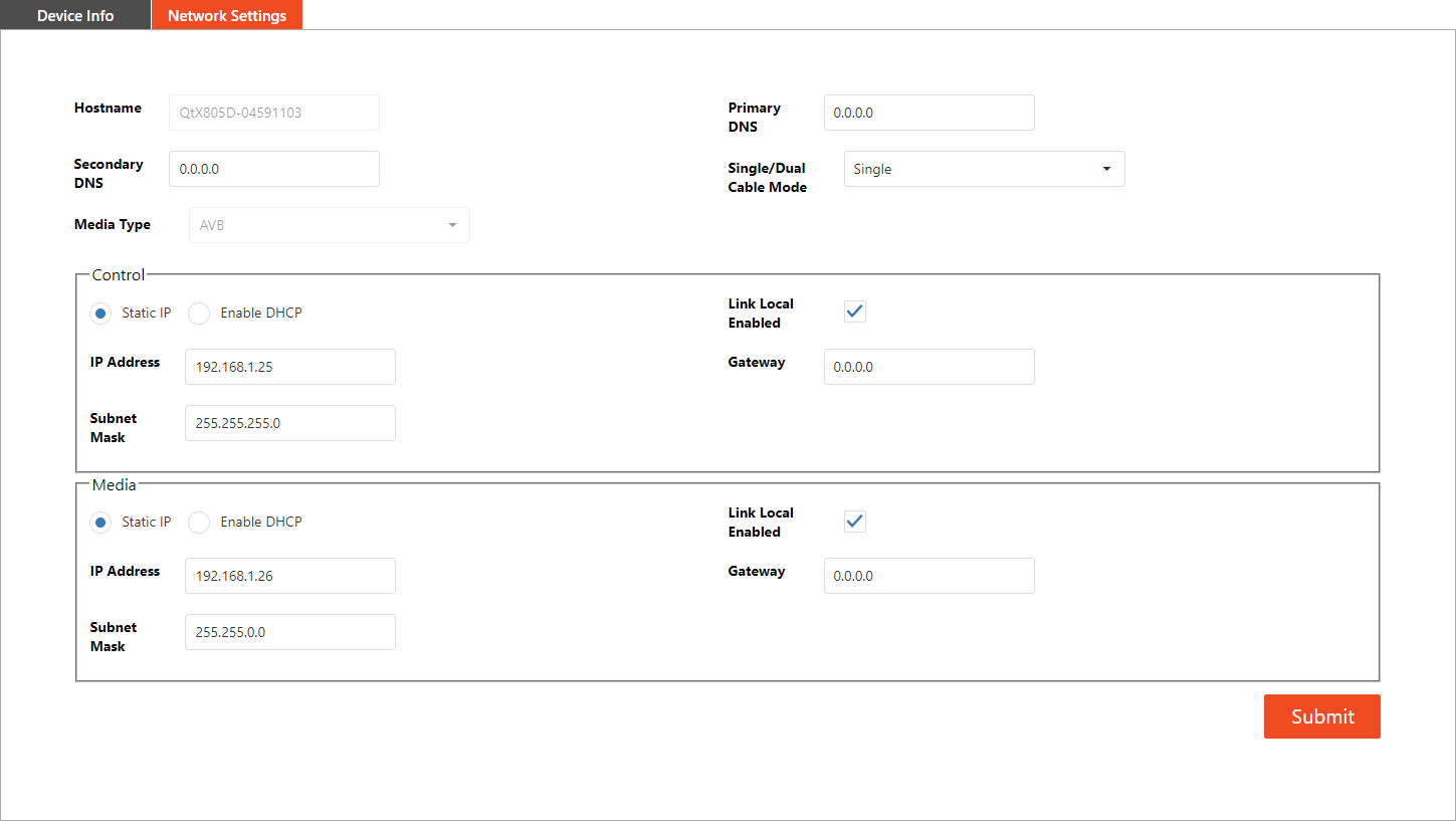
By default, DHCP and link-local addressing (169.254.X.X) are enabled, but one or both can be disabled. All models in the Qt X family support AVB audio, but Dante is only available on the Dante models, which are designated with a "D". For example, a Qt X 300D. A sound masking system can only use one media protocol at a time.
Note: Media network address is active both in Single and Dual cable modes. For example, in single cable mode, if the media address is left at DHCP link-local, while control is set to static IP, any Dante routing will need to be done while on a DHCP link-local IP. In single cable mode, the control and media do not share a common IP address.
Configuring a Qt X System
The steps below are a suggested workflow for configuring a new system with one or more Qt X controllers. This workflow can be changed for user preference.
The Configuration options are all located on the web interface's Configure System page.
Step 1: Adding devices to the system
Discovering and assigning devices
All devices discovered on the network within the same IP subnet range appear under the Discovered Devices tab on the Configure System page.
Each device must be assigned to a sound-masking system to function. To assign devices to a sound masking system, click the check box next to each device to be added and click 'Add To Configuration.' These devices will then all be considered part of the same system and appear on the subsequent tabs and pages.
The Discovered Devices tab includes information indicating the status, serial number, hostname, IP address, and model of each device seen on the network.
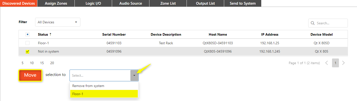
Adding unconfigured devices to an existing system
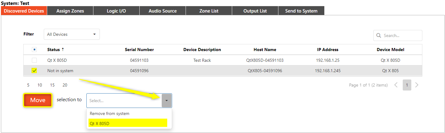
Unconfigured devices can be added to a system using the web UI of a configured device that is already a part of the system. New unconfigured devices will need to be on the same IP subnet to be discovered and available to add.
Configured devices must be cleared of any existing configuration before they are available to add to another system.
When adding unconfigured devices to an existing system, click the check box next to each new device to be added, then select the configured system from dropdown menu. Select "move" to add the unconfigured hardware to the active system.
The status will change after the devices have been moved to reflect the system association of the newly added hardware.
Once selections are complete, select the Send to System tab to submit changes.
Note: Devices may also be removed from an active system using the same process. This allows Qt X devices to be removed without clearing the configuration. A device cannot be removed from the system if you are directly communicating with the system using that device.
Step 2: Creating and configuring zones
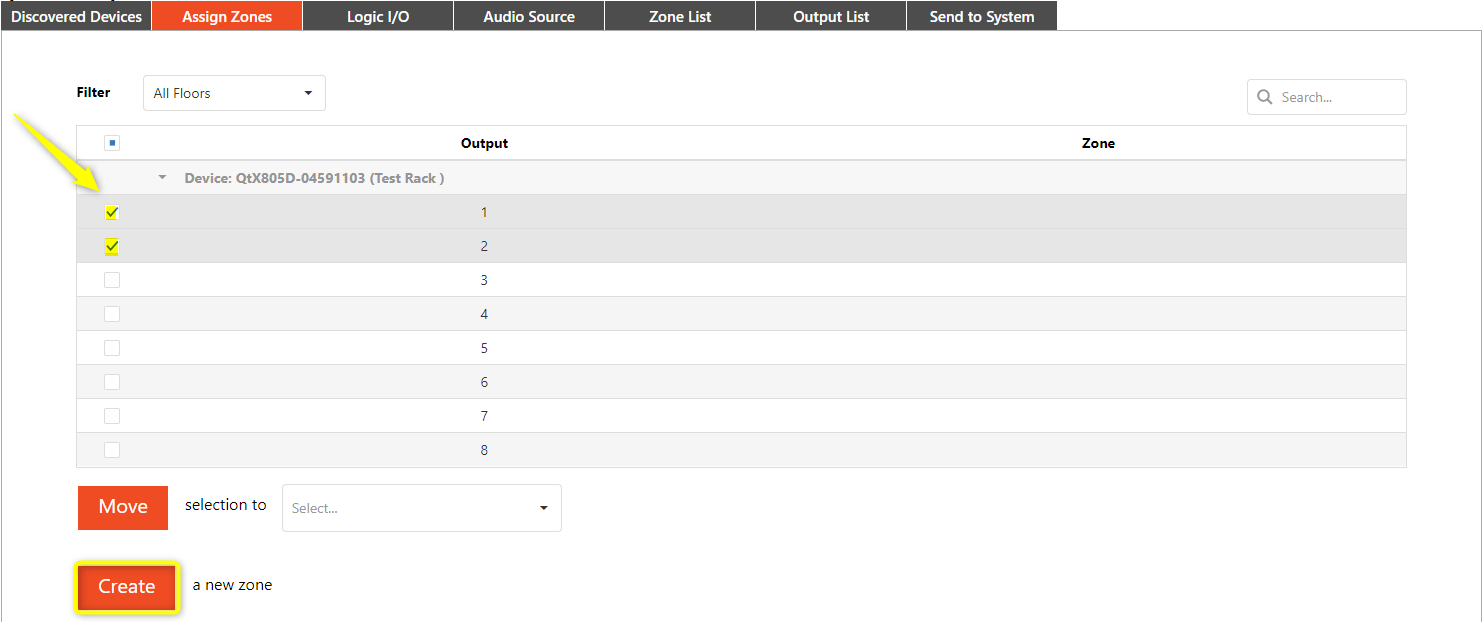
The Assign Zones tab is used to associate outputs on the device(s) to the sound masking zones in a system. A zone should be organized by the physical location of the installed emitters within a space. For example, in an office, Zone 1 could be the reception and waiting area, while Zone 2 could be the open office Space. One zone can consist of multiple outputs from different controllers with different speaker types.
Creating Zones
To create a new Zone, select the desired output(s) for the Zone and click "Create."
Configuring the zone
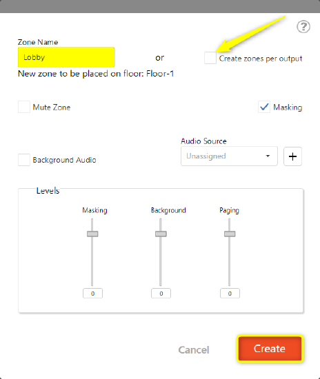 After creating a new zone, a pop-up window will appear with options for configuring the zone.
- Zone Name: Each zone should be named to match the physical space it covers for ease of identification.
- Masking Option: The 'Masking' option is selected by default. This enables the sound-masking audio to play in this Zone.
- Uncheck this option if only audio playback or paging will be used in this zone.
- Background Audio: The 'Background Audio' option is not selected by default.
- To enable background audio playback, check the option and choose an Audio Source from the drop-down list as the audio source for the Zone.
- Click the adjacent "+" icon to create a new Audio Source
- See Step 4 for an explanation of the various options.
- Levels: Sound masking, background audio playback, and paging source levels in the Zone are set relative to each other.
Click the 'Create' button once the zone is configured.
Create zones per output option: This option in the top right corner assigns a unique zone to each selected output and is only recommended for single-controller systems. When this option is checked, each selected output will be assigned to its own zone in numeric order once the Create button has been clicked. For example, Output 1 is Zone 1, Output 2 is Zone 2, etc. If four outputs were selected, four unique Zones will be created.
Step 3: Assigning and moving outputs, adding new devices
Assigning outputs to a zone
- Select the checkbox of the outputs to be assigned.
- Select the zone from the dropdown menu next to the "Move" button.
- Click the "Move" button to associate the selected outputs with the zone.
The Zone column will update to reflect the selected zone.
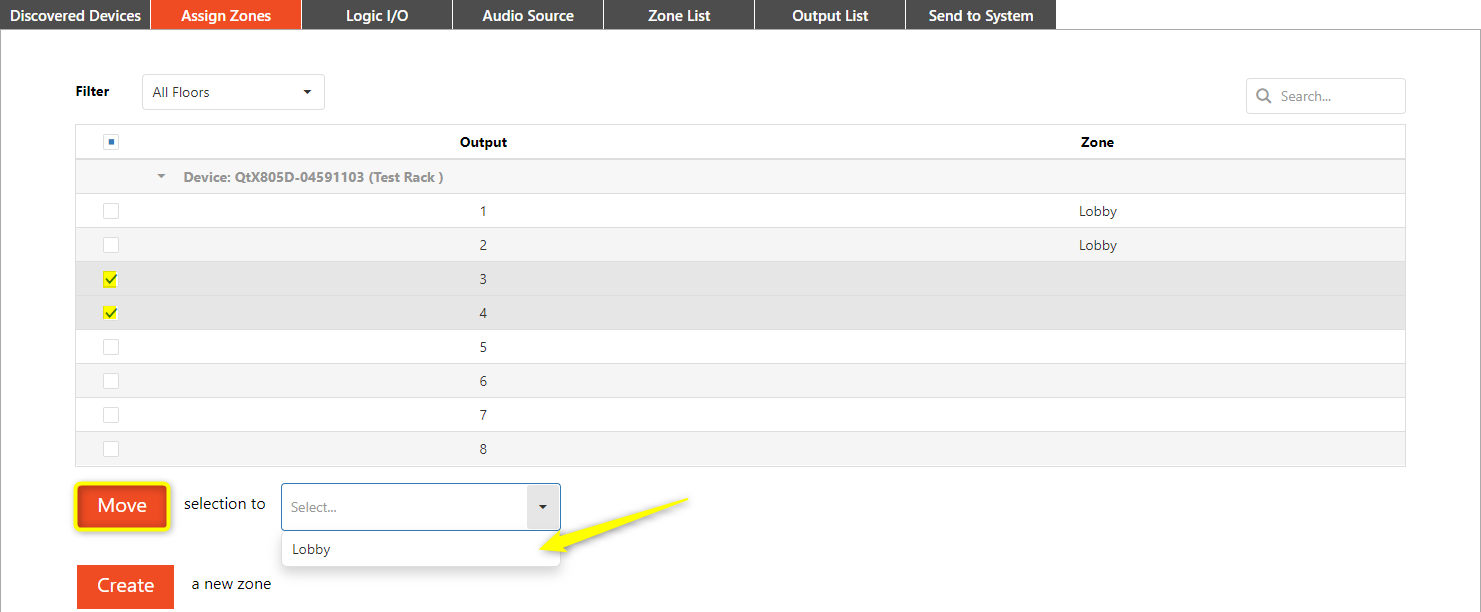
Moving outputs to a different zone
- Check the boxes next to the outputs to be moved.
- Select the zone that outputs will be moved to from the drop-down menu.
- Click the "Move" button.
Adding new devices
If you are adding new devices to an existing system:
- Check the boxes next to the devices.
- Then select a system to assign them to using the drop-down menu.
- Then click the "Move" button.
The Status column will update with this new assignment.
Step 4: Configuring Logic I/O (Optional)
Logic ports on each Qt X device can be configured as needed and trigger actions across various devices in the same system.
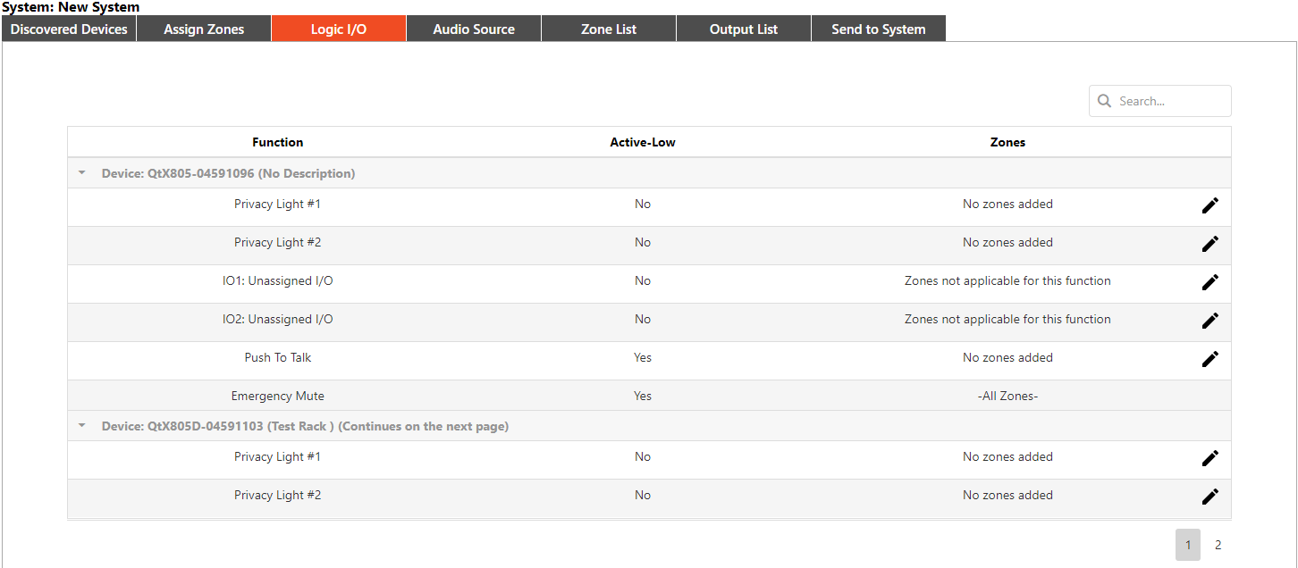
To configure logic ports in the Qt X system, navigate to the Logic I/O tab. Each device in the system will be listed by serial number and opening the device will display the following options:
- 2 Privacy signage connections
- 2 GPIO ports
- 2 contact closures
- Push to Talk
- Mute
Select the logic port you want to configure and click the pencil icon next to it. Depending on the logic port you're configuring, you will be able to edit various settings.
- Privacy 1 & 2 are for the Qt-series light panels that indicate the status of sound masking. These Logic I/O ports do not have any audio functions or priority, they may only be assigned to a selected Zone and set to activate or not. To activate the privacy lights, Sound Masking must be enabled, must not be currently muted, and set higher than -30dB.
- The GPIO ports allow a user to select any audio devices assigned in the Audio Sources tab. 'Unassigned
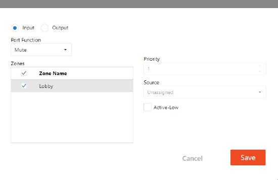 I/O' will select by default. When configuring either IO1 or IO2, you can decide between using the port as an Input or an Output.
 - Input: If selected as an Input, the drop-down selections are Mute and Push to Talk.
- Output: If configured as an Output, the drop-down selections are Mute and Talk Now.
- Selecting Active Low is always available on the GPIO ports to trigger the port off of a Low signal rather than a High signal. Priority may be configured and a one or more zones can be configured to be controlled by the selected IO port.
- Push to Talk is a paging station function and is therefore set automatically as an input (not editable). You may select active low as a logic trigger and may select the audio source type from the drop-down menu. The priority can be changed and one or more zones can be configured to be controlled by the contact closure.
- Emergency Mute is a dry contact closure that triggers when the circuit is closed (Active Low). An Emergency Mute contact will propagate to all controllers in a system and will mute all sound masking zones, background music sources, and paging. Once the contact is opened again, the Emergency Mute will disable and unmute all audio sources.

Step 5: Configuring Audio Sources (Optional)
Audio sources can be added and edited under the Audio Sources tab, including background music and paging source. Any audio source in a sound masking system, whether coming in through an analog input or the media network, will be available to send to any configured zone in the system under the Zone List tab.
Creating Audio Sources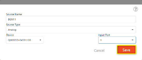
To add an audio source, select the 'Add Source' button. The source name can then be edited and the Source type assigned, choosing between analog inputs or AVB or Dante network media sources based on the device model.
- For analog inputs, a device hostname must be selected, then one of two in-ports on the back of the Qt X device.
- For AVB or Dante streams, enter the stream name to bring it into the system.
Once all the parameters are, click the Save button to create the new audio source.
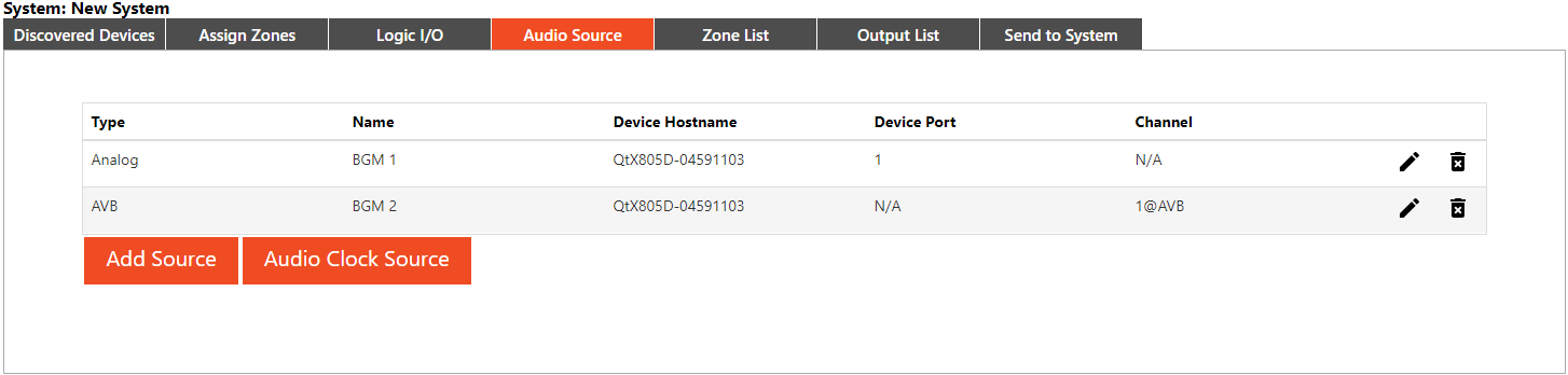
All configured source audio inputs will be listed by Type. All Qt X controllers can host 2 analog and 6 networked media inputs (AVB or Dante).
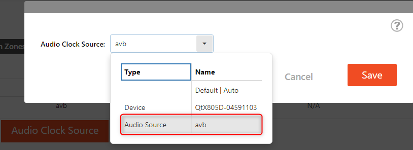
Note: When assigning an external AVB or Dante source as the Audio Clock Source, it must be set to sync to the external device. To assign, click the audio clock source button, and then assign an external device from the dropdown menu.
Step 6: Assigning audio sources to specific zones (Optional)
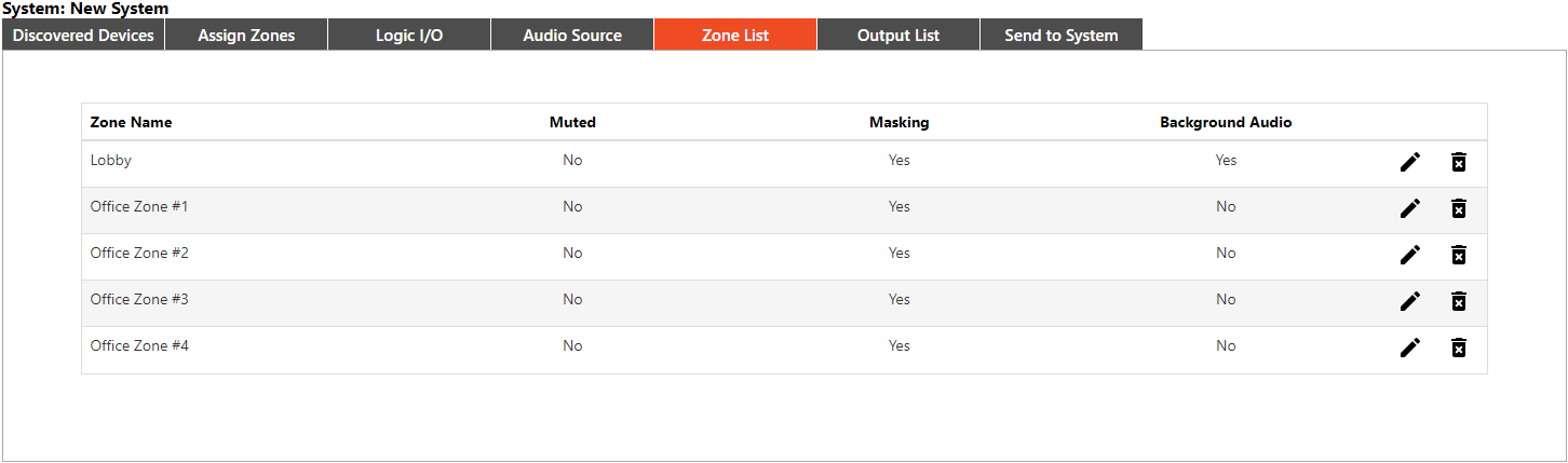
To assign an audio source to specific Zones, navigate to the Zone List tab. This tab contains a list of all created Zones as well as the three default zones.
- Select the pencil icon for the zone the source will be assigned to. The same fields available when creating the zone will be available.
- Select the desired source from the Audio Source dropdown.
- Optional: check the Background Audio checkbox for any background music sources to assign the appropriate priority to the source for paging and muting.
- Optional: Clicking the "+" icon creates a new audio source. Faders can be used to set the relative levels between the various sources in the Zone.
- Once the audio sources are assigned, click the Edit button to apply the changes.
Step 7: Review and edit zones (Optional)
Zones can be reviewed and edited under the Zone List tab.
- Click the pencil icon to edit the zone
The fields available during zone creation can all be edited except for zones created using the Create Zones per Output feature. The automatically generated numerical names for these cannot be changed.
Audio sources can also be assigned here. Additionally, zones can also be deleted from this list, and an overview of the zone's mute state, masking, and background states is available.
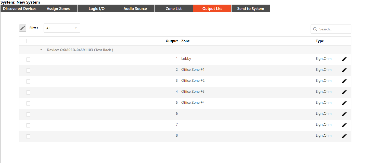
Step 8: Configuring Output Settings
The Output List tab shows a list of all outputs on each device in the system that the zones the outputs are tied to.
 Click the pencil icon
  to open the output settings window.
 - Select the correct emitter or speaker type for the output using the dropdown menu:
- Active or passive emitters for the Qt X 300/D and 600/D models
- 4 Ohm, 8 Ohm, or DS1320 speaker types for the Qt X 800/D and 805/D models
Please note that the emitter type on the Qt X 300/600 models is configured for both runs of each output. A single Zone can have a mix of passive and active emitters in it, so it is important to configure each output correctly.
Click the Save Changes button to apply.
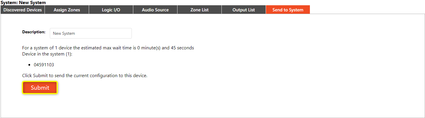
Step 9: Sending the Configuration to the system
Once all the settings are configured, the configuration file must be sent to the system.
- Navigate to the Send to System tab.
- Write a short description of the system in the Description field.
- Verify that the correct devices have been assigned to the system with each device's serial number listed.
- An estimate of the maximum wait time to load the configuration to all devices in the system will be displayed.
- After verifying the system and device information click the Submit button.
This sends the configuration to the devices and activates the system.
Editing the System Settings
Once the configuration has been sent, live adjustments can be made to the configuration using the System Settings page. The settings are located under the following tabs.
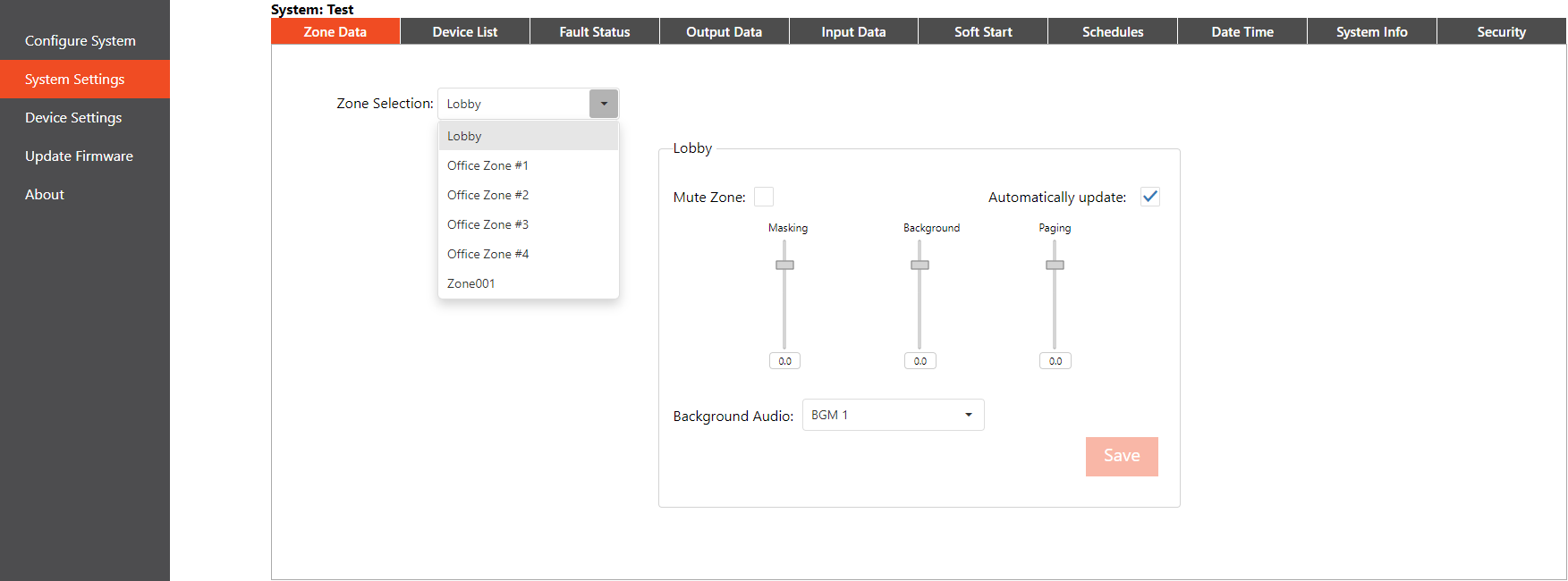
Zone Data Tab
Each zone's settings can be changed on the Zone Data tab. Select a zone by using the Zone Selection dropdown field.
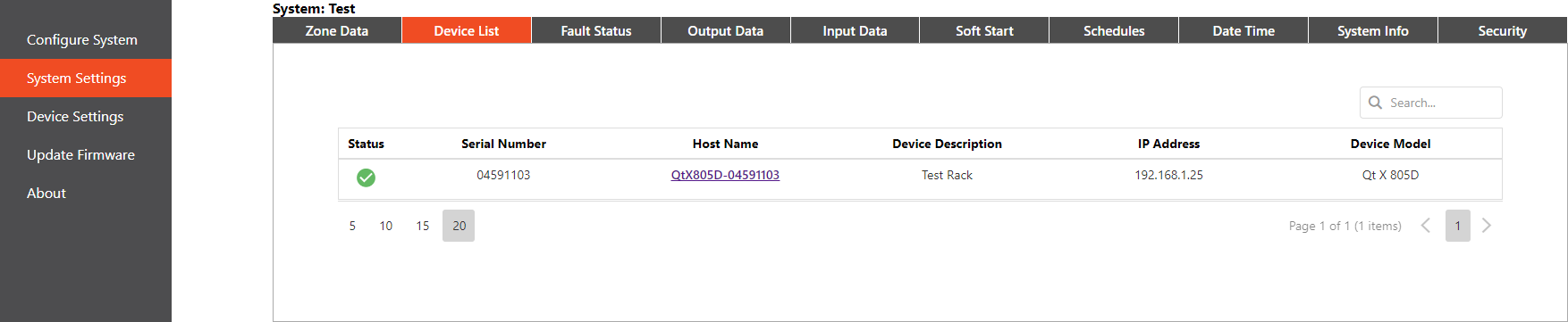
Device List tab
The Device List tab shows devices currently connected to the system and gives information including the serial number, host name, device description (if entered), IP address, device model, and firmware version. The list is read-only.
Click on a device's hostname to view the full range of device information as well as change the device description. This also directs the browser window to that device's web user interface.
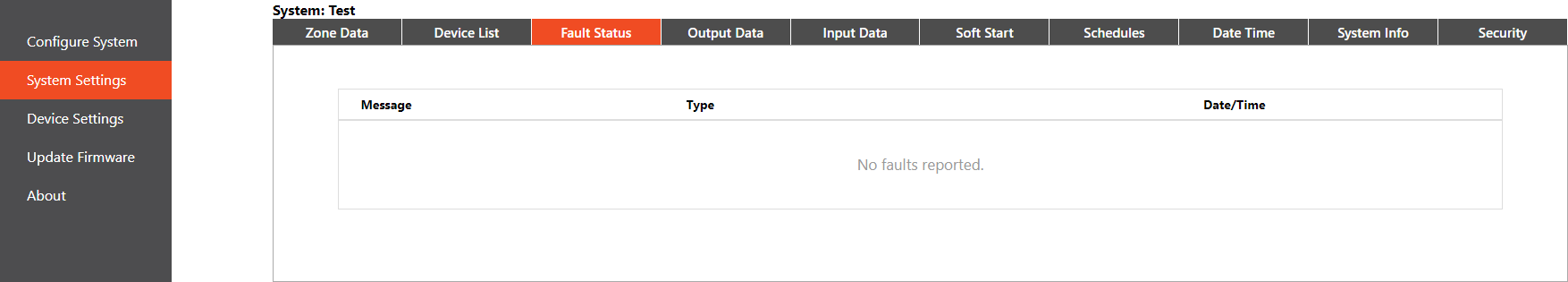
Fault Status tab
The Fault Status tab indicates if a device is operating normally or if faults are present. Errors are described in brief messages, the message type describing whether it is a device or system error. An abbreviated version of the fault message may also be displayed on the front panel of the device.
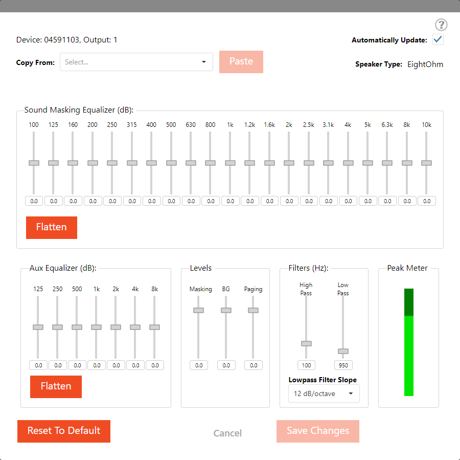
Output Data tab
Device audio outputs can be adjusted on this tab. Click the fader icon to select the emitter type for each zone (based on the sound-masking device-type) and adjust the audio settings:
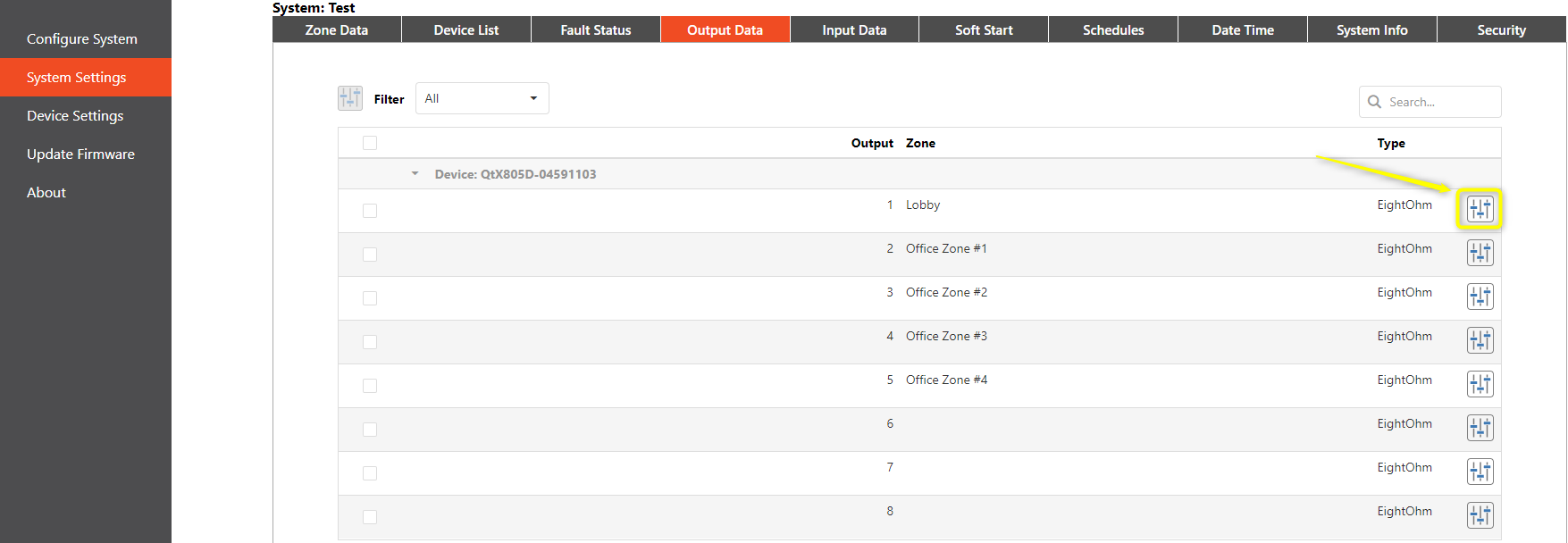
Once an output is selected, equalization, level, filters, and metering are shown per zone. Aux equalizer applies to both analog source inputs.
Input Data tab
Preamp gain can be adjusted and phantom power enabled for appropriate devices on this tab. A Peak Meter indicator is also provided for the input.

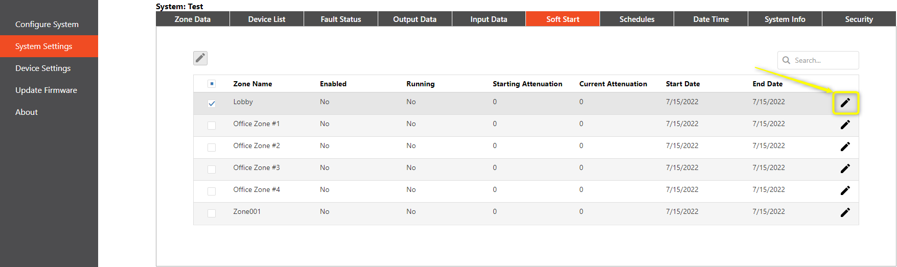
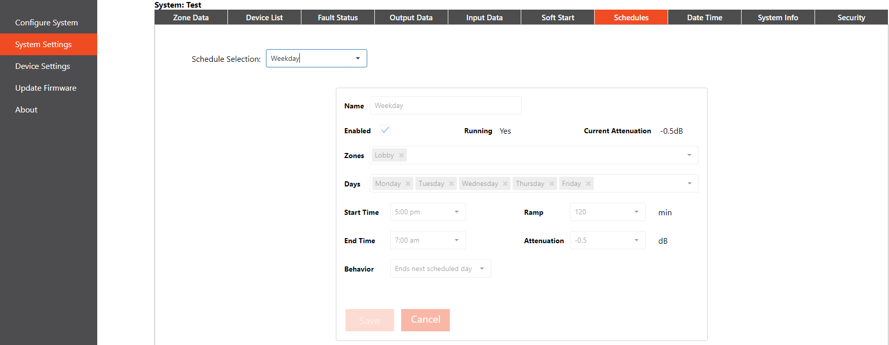
Soft Start tab
Sound masking can be ramped up (slowly increased) in a zone to avoid a distracting experience for occupants when sound masking is first introduced to the space. The Soft Start tab shows whether or not the soft start function is enabled for each zone along with the start and end dates for a slow ramp-up. To edit or configure a soft start for a zone, click the associated pencil icon.
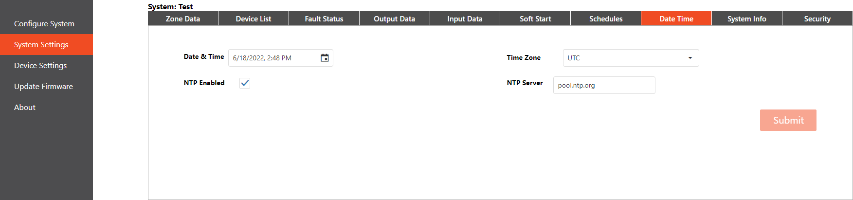
Date and Time tab
The system time settings can be adjusted on this tab, including enabling Network Time Protocol (NTP) to synchronize clocks as required. The time can be manually adjusted, a time zone selected, and (if NTP is enabled), a server can be chosen to sync the time to.
Click Submit to apply changes.
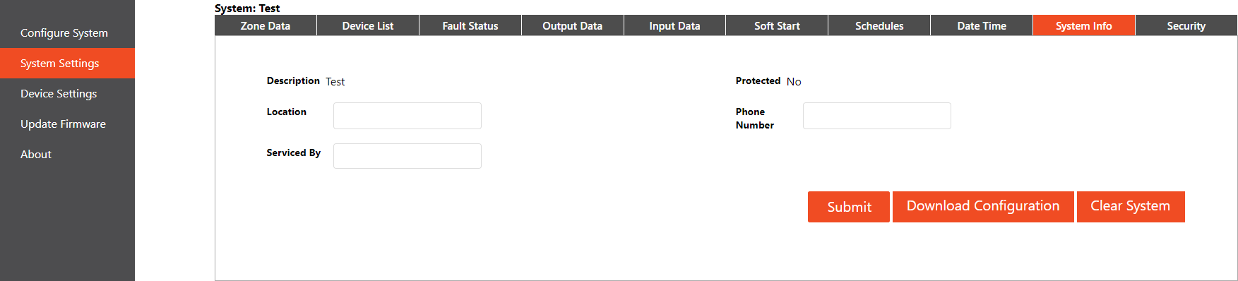
System Info tab
Information describing the system can be viewed and edited on this tab. Click the "Submit" button to save changes to the description. Additionally, the system configuration can be cleared or a configuration downloaded here.
Security tab
Security levels set on this tab protect the system from unauthorized changes.
- The Admin role must be created and assigned before any additional logins can be created.
- After saving the Admin login, create any additional logins and assign user roles
- A Logout button appears on the side pane after the Admin login is created.
- User names must be alpha-numeric without spaces.
- Passwords must be between 8-64 characters.
- User names are not case-specific.
IMPORTANT: Document the admin user name and password. These cannot be recovered if lost.
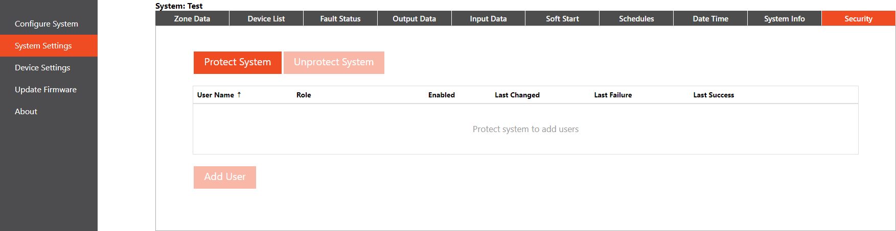
The Admin-level login must be used to unprotect a system. The Un-protect System option will be available in the Security tab of the System Settings page. Unprotecting the system removes all user accounts and users will no longer be prompted for login information when accessing the system.
| User Role | Permissions |
|---|---|
| Administrator | Full access - may create users, un-protect/protect a system, make changes to the system, etc. |
| Commissioner | Same permissions as the Administrator except they may not create new users or make changes to the network protocols. |
| User | Some ability to change settings, such as zones, time/date, scheduling, etc. |
| Viewer | Read-only; cannot make any changes to devices or systems. |
Updating Firmware on a Qt X System
Updates using the web interface only apply to the individual controller currently accessed. These are not system-wide changes. Current firmware is available for download from biamp.com or support.biamp.com
Select the Update Firmware tab and then Choose a File to select the downloaded firmware.
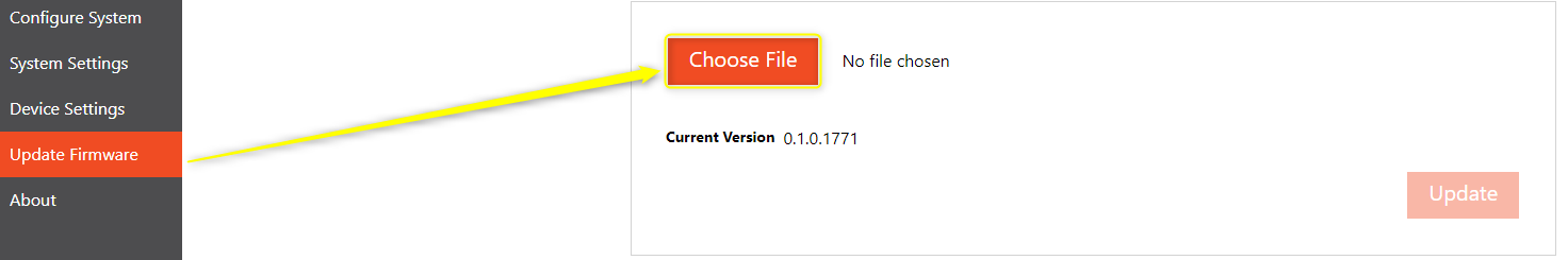
After selecting the appropriate file (.qfa format, download the latest here) from the file browser, it will populate with the name for confirmation. Click Update to begin the update process. A status bar will indicate progress and a dialog box will indicate when the firmware update has completed.
Reboot: A notification will appear at the end of the update. The controller will then reboot. Audio outputs from the controller will temporarily stop while rebooting.