Qt X System installation guide
This article summarizes Qt X cabling and emitter guidelines for use as a convenient online reference as well as answering high-level questions related to zone run limits, cable types, and distances.
The full installation and operations guide goes into greater detail on these topics and can be found here: Qt X Installation-Operation Guide

![]()

System size limits
The upper limits on Qt X devices and zones in a single system as of the 2.4.0 firmware July 2024 release:
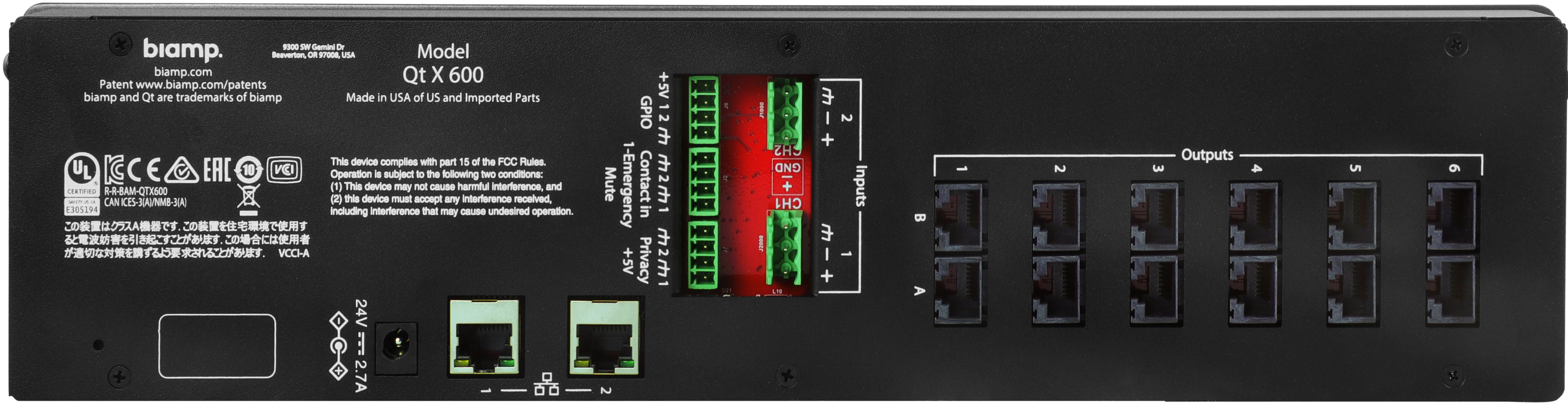
- 250 Qt X Devices in a system. This includes any combination of Qt X 300, 600, 800, and 805 controllers, both standard AVB or "D" Dante versions.
- 440 Total zones in a Qt X system file
- 110 NPX Network Paging zones (Aug 2023 update)
- Minimum Requirements: Software v2.2.0, Qt X firmware v2.2.0, NPX firmware v1.2.0
- Up to 16 NPX stations of any type or combination may be supported by a Qt X system.
- Any Qt X device can "host" or proxy up to four (4) NPX stations.
- NPX only supported with Qt X controllers running in single cable mode.
QT X software download
Installation considerations
Qt X 300 and 600 systems
- Output runs must have the same device type (Standard or Active Emitters) and will share the same sound masking settings. The cabling runs must be configured to prevent any signal interference among the 4 channels along the layout.
- Differences in ceiling height of more than 6" (152mm) need to be connected as separate outputs because sound masking levels will be different.
- Each output's sound masking levels can be individually controlled and then assigned to networked zones with additional controls applied to the
whole zone. - Active Emitters are recommended for systems supporting background music or paging in addition to masking applications.as they have a max SPL of 74dBA compared to the 56dBA max SPL for music and paging when Passive Emitters.
Qt X 800 and 805 systems
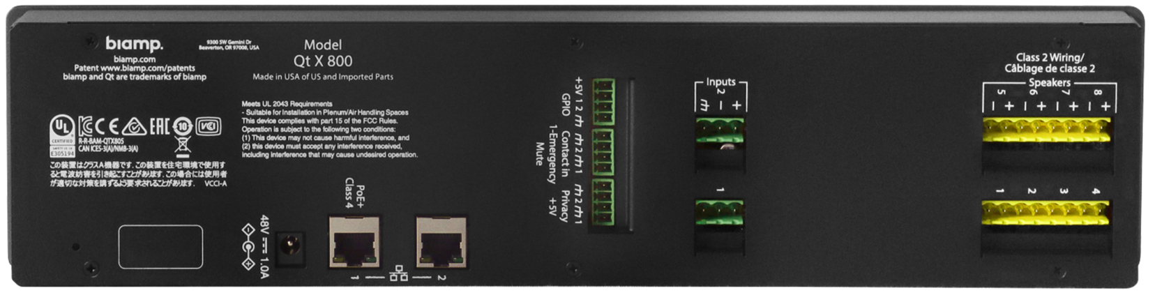
- Each Qt X 800/805 controller has eight (8) outputs. Class 2 speaker output runs are limited to single* 4Ω and 8Ω speakers (DS1357, DS1398) or DS1320 active emitters.
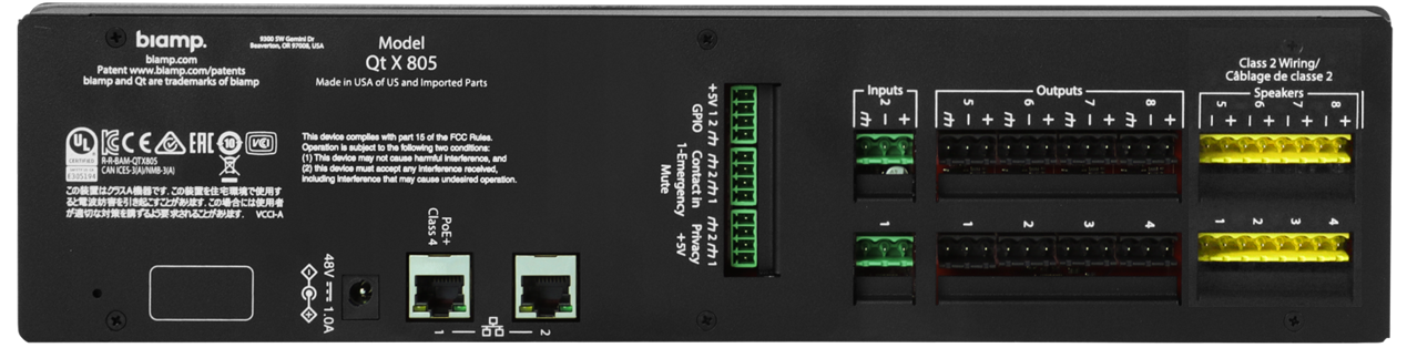
- The Qt X 805/805D has an additional set of 8 line level outputs (mirroring the Class 2 outputs) that can be connected to amplifiers to run DS1339/ DS1390 70V sound masking loudspeakers.
- The Qt X 800/800D is designed for installation in the plenum space and requires a PoE+ power supply (not included) for operation. The Qt X 805/805D is a rack-mounted unit and comes with a power supply.
- Since the controllers are networked, multiple outputs sharing the same environmental, area, and sound masking characteristics can be combined in the same zone, which can then be configured in the software or via the onboard web interface.
*Note: Two DS1357 or DS1398 speakers may be daisy-chained on a single output for specific coverage scenarios but are not able to be controlled/tuned individually in this instance.
Wiring and Cabling
Qt X 300 and 600
Cabling for Active and Passive emitters is included in designated lengths (16, 22, or 30 feet) depending on the emitter bundle ordered.
Sort the cables by length and label by output and run for installation ease. If you need to make a custom-length cable, please note the following:
- Use solid conductor 24 AWG CAT-3, 5, 5e, 6, or 7 cable that meets local code requirements.
- If the system is installed in a return air plenum, the cable must be plenum rated.
- Shielding is not required. Unshielded twisted pair (UTP) cable is acceptable.
- Snagless boots are not required.
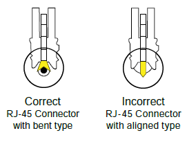
- RJ-45 plugs must use the “bent 3-tine” RJ-45 plugs intended for use with solid core CAT wire. Three-tine plugs can be purchased at a hardware store and from most CAT cable suppliers. DO NOT USE the “aligned two-tine” type intended for stranded wire, as they provide improper contact and may yield intermittent system operation. The diagram shows the cross-section view of both types.
- Field test each cable after fabrication with the RJ-45 connectors (before final installation), with a standard network LAN tester to check for continuity, shorts, and 1:1 (straight through) connection before installation.
- Factory Cables are terminated using EIA/TIA568B standard pinout.
Qt X 800 and 805
Loudspeaker connections from QtX800/805 controllers are facilitated with 18 gauge two conductor stranded audio cable for runs up to 40' (12.2m) in length and 16 gauge two conductor stranded audio cable for runs up to 55' ( 16.8m) in length. Ensure all cabling meets local building code requirements.
Emitter Installation - Qt X 300s and 600 models
Emitter Types
Passive
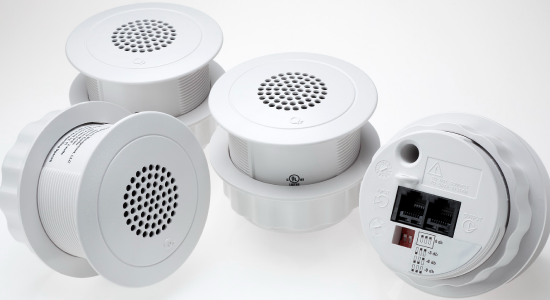
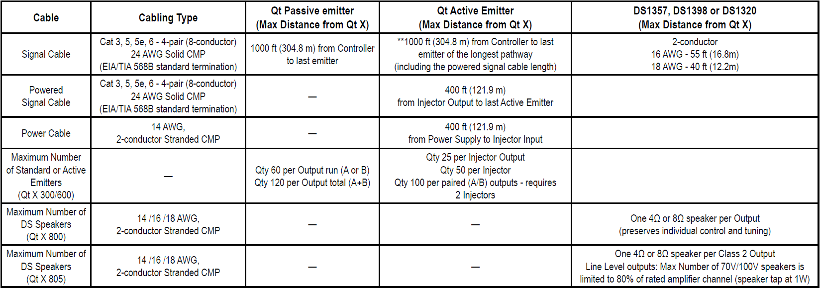
The Qt Passive passive emitter is a passive audio loudspeaker device suitable for sound masking applications. This emitter receives an amplified signal directly from the Qt X control module via a UTP category cabling infrastructure. Maximum sound pressure levels with this type of emitter are 60dBA at 1 meter with a sound masking frequency response of 200Hz to 6.3kHz.
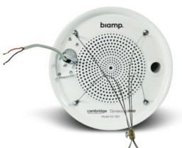
Active
The Qt active emitter is a self-powered audio loudspeaker device suitable for sound masking, paging, background music. This emitter contains an internal amplifier that receives the audio signal directly from the Qt X controller in addition to a direct current voltage that powers the active emitter. Both power supply(s) and power injectors are required for operation in addition to the Qt X. Maximum sound pressure levels with this type of emitter are 65dBA @ 1 meter with a sound masking frequency response of 125Hz to 8kHz. Maximum sound pressure levels for paging and background music are 74dBA @ 1 meter with a frequency response of 105Hz to 16kHz.
Each cable run has a maximum length of 1000 ft (305m).
Emitter quantities
The tables that follow give the number of emitters that may be installed in a given cable run, output, etc. per Qt X device. Each output has two identical runs (A and B). The emitters in both output runs are controlled equally and must be of the same emitter type.
| Qt X 300/300D - Emitter Installation Totals |
| Emitter Type | Per Cable Run | Per Output | Total (3 Outputs)* |
Standard |
60 | 120 | 360 |
Active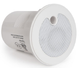 |
50 | 100 | 300 |
IMPORTANT: Do not mix emitter types in the same output.
| Qt X 600/600D - Emitter Installation Totals |
| Emitter Type | Per Cable Run | Per Output | Total (3 Outputs)* |
Standard |
60 | 120 | 720 |
| Active |
50 | 100 | 600 |
* Output total assumes the same emitter type in each output. Total emitter counts will vary per device if both standard and active emitters are present in a system.
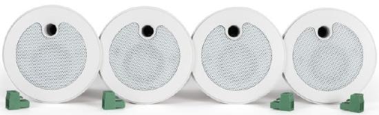
- Active and passive emitters are installed identically. On the passive emitters, the input and output ports are labeled as such: INPUT, OUTPUT. It is critically important that the emitters are wired and or located following the layout and wiring diagram from the Design Team to prevent any signal interference.
- A hole saw bit is included with Qt X 300/600 models for ceiling tile or drywall installation. A hole size of 2.5" (64mm) is required for both passive and active emitters.
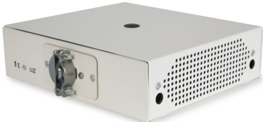
NOTE: For Active Emitters, a Qt Power Injector (purchased separately) will need to be installed directly adjacent to the first emitter. Each output on the power injector can power up to 25 Active Emitters (up to 50 for each PI-AE). A Qt Power Supply (also purchased separately) is necessary to power the injectors and can power up to three (3) Qt power injectors.
Standard and Active Emitter Spacing
| Emitter Mounting Height* |
Emitter Spacing - 2'x2' ACT, Open or Solid-Surface Ceilings | Emitter Spacing - 2'x4' ACT Ceilings |
Min Distance from Wall or Obstacle |
Max Distance from Wall or Obstacle |
| < 8' – 9' (2.4 2.8m) | 8' x 8' (2.4 x 2.4 m) | 8' x 8' (2.4 x 2.4 m) | 2' ( .6 m) | 4' (1.2 m) |
| 9' – 10' (2..8 – 3.1 m) | 10' x 10' ( 3.1 x 3.1 m) | 10' x 8' ( 3.1 x 2.4m) | 2' ( .6 m) | 5' (1.5 m) |
| 10' – 11' (3.1 – 3.4 m) | 10' x 10' ( 3.1 x 3.1 m) | 10' x 8' ( 3.1 x 2.4m) | 2' ( .6 m) | 5' (1.5 m) |
| 11' – 12' (3.4 – 3.7 m) | 12' x 12'( 3.7 x 3.7 m) | 12' x 12' ( 3.7 x 3.7 m) | 2' ( .6 m) | 6' (1.8 m) |
| 12' – 14' (3.7 – 4.3 m) | 12' x 12' ( 3.7 x 3.7 m) | 12' x 12' ( 3.7 x 3.7 m) | 2' ( .6 m) | 6' (1.8 m) |
| 14' + (4.3 m+) | Contact Biamp Support | Contact Biamp Support | 2' ( .6 m) | 7' (2.1 m) |
*Mounting height may not always be at the ceiling height
NOTE: Emitter type selection must be made on an output-by-output basis using the web user interface or the Qt X software. Passive emitters are the default
type for the Qt X 300/600 models. Do not mix emitter types in the same output.
- The Standard Passive Emitter which has a maximum output of 56dBA for masking, and the Active Emitter, which has wider frequency range and has a maximum output of 74dBA for masking, music, and paging. Your source type and the environmental use case will determine which type of emitter you will need. For background music, environments with a very low noise floor, such as doctor's offices, law firms, or waiting rooms, can be approached with either type of emitter. If the environment has a higher noise floor and louder levels are needed from the emitter to produce audibly comfortable music, than the Active Emitter must be utilized as it is capable of producing higher levels of sound in the space.
- If paging is required, only Active emitters are required as they produce a higher level of sound to better allow pages to be heard and understood. Standard emitters do not have enough output to effectively meet the needs of a paging system.
Speaker Installation - Qt X 800 and 805
Speakers Types
The DS1357 and DS1398 models are indirect loudspeakers.
- The DS1357 is designed to be suspended by a central wire in open ceilings. This speaker is 8 Ohm and can be daisy-chained with another speaker of the same model type for a maximum of 2 per output. Most designs will just call for a single speaker per output.
- The DS1398 can be installed under floor or over ceiling tiles. This speaker is 4 Ohm and cannot be daisy-chained.
The DS1320 is an active emitter with a 2-wire connection and can be installed in drop ceilings. The maximum cable distance for each (DS1320) output is 55 ft (16.8 m) when using 16 AWG wire.
DS1357 Installation
-
 Run 2-conductor wires from the controller to each speaker location.
 - Install the speaker at the designated height by suspending it with a steel cable (installer supplied) from the center eyebolt. Each speaker should be installed at the same height (from the floor), consistent with the other DS1357 speakers in the space.
- Connect the conductors from the speaker lead matching the positive and negative conductors to the home run cable and secure with approved connectors. The signal cable must have enough slack to keep it from acting as part of the device suspension.
- Once the system is powered with the output assigned to a zone and configured, the signal intensity may be further adjusted using the Qt X software or web interface.
DS1398 Installation
- The speaker may be installed in select raised access floor systems or in shallow ceiling plenums. An optional mounting bridge is availa
 ble for use in plenums where other sound masking speakers aren't feasible. Please contact the Sound Masking Design team for specific information on use in under-floor systems.
 - Run 2-conductor wires from the controller to each speaker location.
- Remove the plate to access the speaker lead. Run the incoming cable through the strain relief and connect the conductors matching the positive and negative conductors to the home run cable. Secure connections with approved connectors and tuck them back into the opening. Reattach the cover.
- Once the system is powered with the output assigned to a zone and configured, the signal intensity may be further adjusted using the Qt X software or web interface.
DS1320 Installation
- Run 2-conductor wires from the controller to each speaker location.
- This emitter can be installed in a ceiling tile the same way as the Qt Active emitter but must use a 2-wire connection from
 the controller. The RJ45 jacks and internal amplifier is disabled. The ceiling tile should have a hole cut in the center of the tile.
 - The emitter can be pushed through the front of the tile and secured with the knob. Strip and secure the incoming cable conductors in the euroblock connector. Plug the connector into the jack in the rear of the emitter.
- Once the system is powered with the output assigned to a zone and configured, the signal intensity may be further adjusted using the software or web interface.