Netgear NMS-NG10GPX-AVB (M4250-10G2XF-PoE+) switch configuration and topologies
This article provides an overview of the Netgear M4250-10G2XF-PoE+ switch when resold with the Biamp part number NMS-NG10GPX-AVB. This switch supports AVB installations that include Qt X and Tesira products an comes configured with a default file allowing for out-of-box functionality with the ability to scale up to a defined system limit.
Specification: This specification outlines the features of the switch, default configuration, and supported topologies as recommended by Netgear. All tested topologies recommended by Biamp will include the NMS-NG10GPX-AVB switch shown in a single or small scalable daisy chain/bus topology.
Netgear Support: Netgear offers design support through their Pro AV Design Services group. Biamp recommends contacting them at ProAVDesign@netgear.com for network design support on any topologies that are not listed as tested by Biamp or that require mixing M4250 switch models within a design.
Default Configuration File: Biamp Default NMS-NG10GPX-AVB
Overview
The Netgear M4250 AV Line of switches provides a range of configurations supporting multiple audio and video Ethernet protocols, including AVB, Dante, and AES67. In addition to a wide variety of industry-standard networking features, this line of switches includes specific features tailored to the AV industry.
- Switches are certified by the Avnu Alliance for AVB support.
- Dedicated AV web-based GUI interface that allows the application of port-based profiles for different AV protocols to simplify switch configuration for different supported AV protocols.
- Dedicated console (serial and USB) and out-of-band network ports for configuration and management
- Support for up to 256 AVB streams
- Out-of-box switches will be running a default Biamp config file that includes all the AVB profile settings for proper operation using default VLAN 2 for AVB traffic.
- Spanning tree limits daisy chain/buss topologies to 7 switch hops. Biamp recommends max 6 switches in a plug-and-play system not requiring additional configuration.
- Designs incorporating different switch models, or mixed networks or VLANs will require design assistance from Netgear.
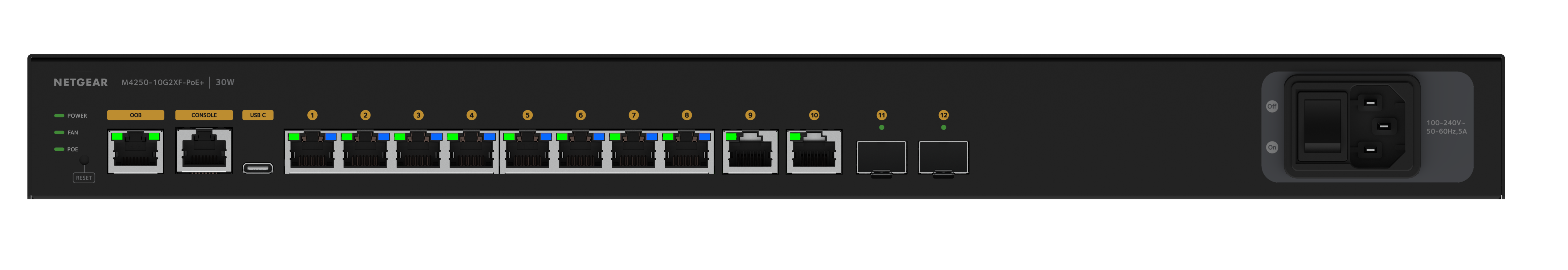
- (8) 1G PoE+ ports, 240W total budget to support up to (8) Qt X 800/800D controllers per switch.
- (2) standard 1G LAN ports to support Auto-Trunk, additional non-PoE Qt X controllers, or AVB/Dante input devices.
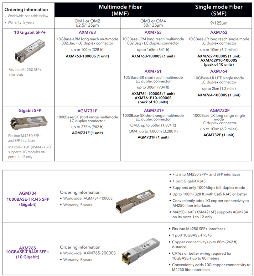
- (2) SFP + ports to support switch topology expansion.
- Fiber media converters are not supported for QT X controllers connected to SFP ports while running in AVB configurations.
Notes:
- AVB license will be installed and activated on each switch when shipped. (included free after FW 13.0.4.17)
- Netgear switches will be updated to the latest public firmware release available when shipped to Biamp. Check the Netgear download center page for latest version available to update as needed.
- AVB is not supported over LAG.
- Tested support for up to 6 switches via Netgear auto-trunk feature.
Auto-trunk
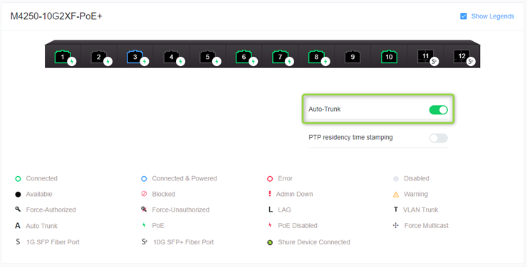
Auto-Trunk provides an effortless ability to configure multiple VLANs onto an uplink Ethernet port or any unused Ethernet port. By simply setting up the pre-configured network profile or VLANs on a specified port, the M4250 automatically configures the enabled, unused Ethernet port (preferably used for interconnect) to support all the VLANs configured on the switch.
Default Configuration
A default AVB configuration will be loaded on the switches that ship from Biamp along with an active AVB license. This configuration follows the normal recommended configuration as shown in Netgear-related Cornerstone articles.
This default enables AVB on all ports to primarily support AVB and will only assign ports to default AVB VLAN 2 if an AVB device is connected. Testing has shown in a single switch setup that if used for Dante traffic, no additional steps are needed and if a non-AVB device is connected it will not join the default AVB VLAN.
If additional Dante-specific settings are needed, the profile may be changed to Audio Dante: via the web UI of the switch.
Default Configuration File: Biamp Default NMS-NG10GPX-AVB
Switch connectivity
-
Network to any of the Ethernet network ports through the management VLAN
-
Network to the dedicated Out-of-Band (OOB) network port
-
Serial or USB connection using the dedicated console or USB port. Note that the console connection requires a specialized serial rollover cable and a Type-C USB cable.
Ethernet Connection
- Configure your computer with a static IP address.
- For access over the OOB port, use an IP address in the 192.168.0.0/16 subnet. (ie. 192.168.1.100/255.255.0.0)
- For access over any other Ethernet port, use an IP address in the 169.254.0.0/16 subnet. (ie. 169.254.100.201/255.255.0.0) Note that you can use “obtain IP address automatically” on the computer adapter and it will self-assign to a link local address in the proper range.
2. Launch a web browser and enter the default IP address of the switch in the address field of the browser:
-
For access using the OOB port, enter http://192.168.0.239
-
For access using any other Ethernet port, enter http://169.254.100.100
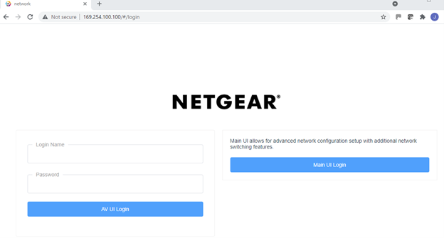
3. Sign in.
-
The main login page has options to access either the AV UI or the Main UI.
-
At the user prompt, log in to the switch using the Login Name admin and Password password.
-
Use these credentials work for both the AV UI and Main UI logins.
-
-
These credentials are part of the default configuration that ships on each switch an can be changed after the first login.
Console Connection
To use the CLI for initial configuration, connect a computer to one of the console ports on the switch.
1. Depending on the connector type at your computer or terminal, and the port that you are using on the switch, use one of the following cables:
-
USB console cable for use with the Type-C USB console port. Note: To use the Type-C USB port, you must install the USB driver on the computer. You can download the driver by visiting https://www.netgear.com/support/download/.
-
Console cable for use with the RJ-45 RS232 console port.
2. Connect one end of the cable to the appropriate port on the switch and connect the other end to your computer or terminal.
3. If you connect a computer to a console port on the switch, start a terminal emulation program:
-
On a computer with a Windows operating system, you can use HyperTerminal, Putty, or Tera Term.
-
On a computer with a Mac operating system, you can use ZTerm.
-
On a computer with a Linux operating system, you can use Minicom.
4. Configure the terminal emulation program to use the following settings:
-
baud rate: 115,200 bps
-
data bits: 8
-
parity: none
-
stop bit: 1
-
flow control: none
Note: A factory reset switch will only require the Login name admin without a password. During the first login, the switch will prompt you to specify a password.
Default Switch Configuration Settings
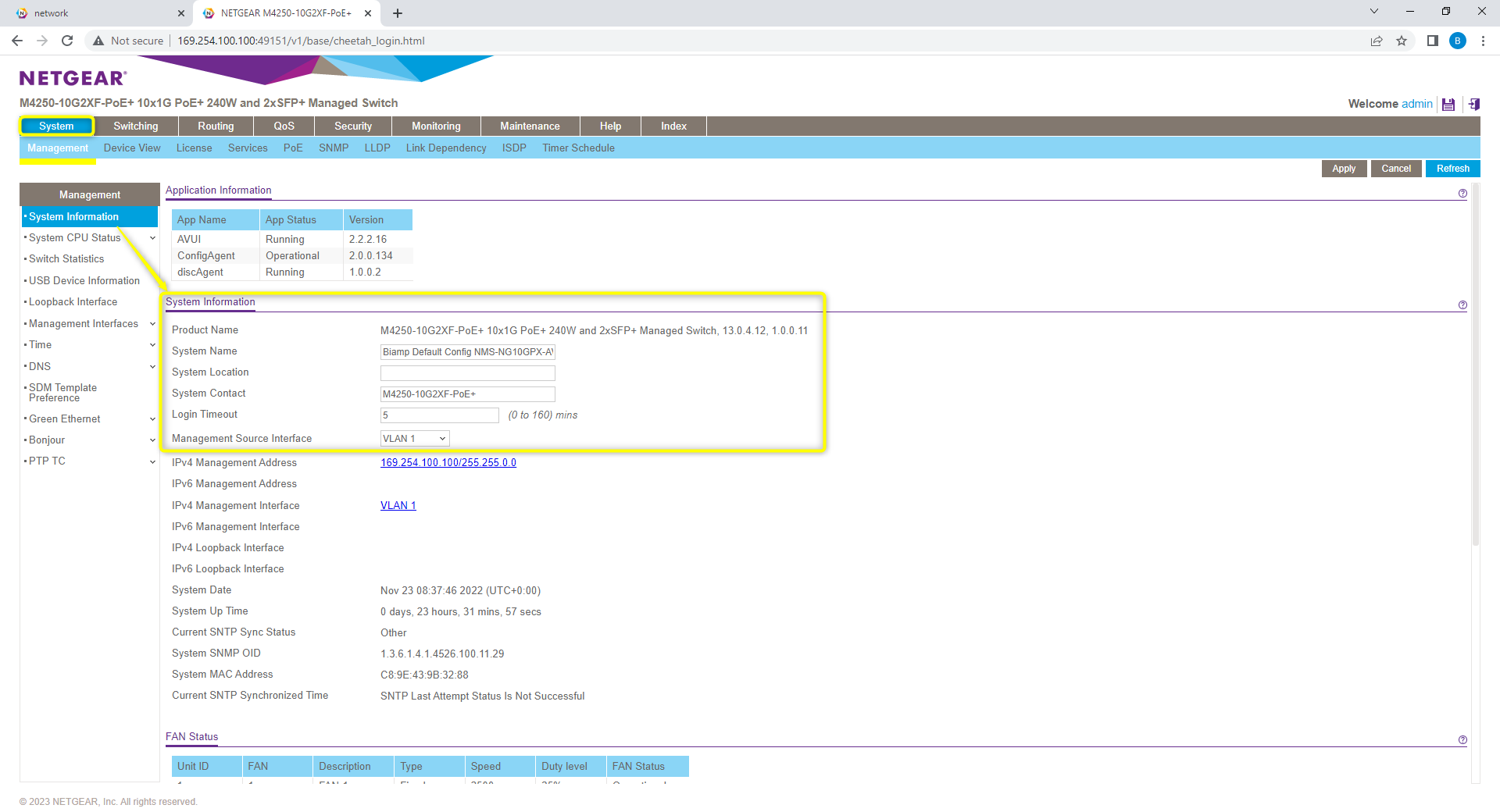
The default configuration should be running on the switch. This may be verified from the System -> Management tab that M4250-10G2XF-PoE+ is running the Biamp default configuration.
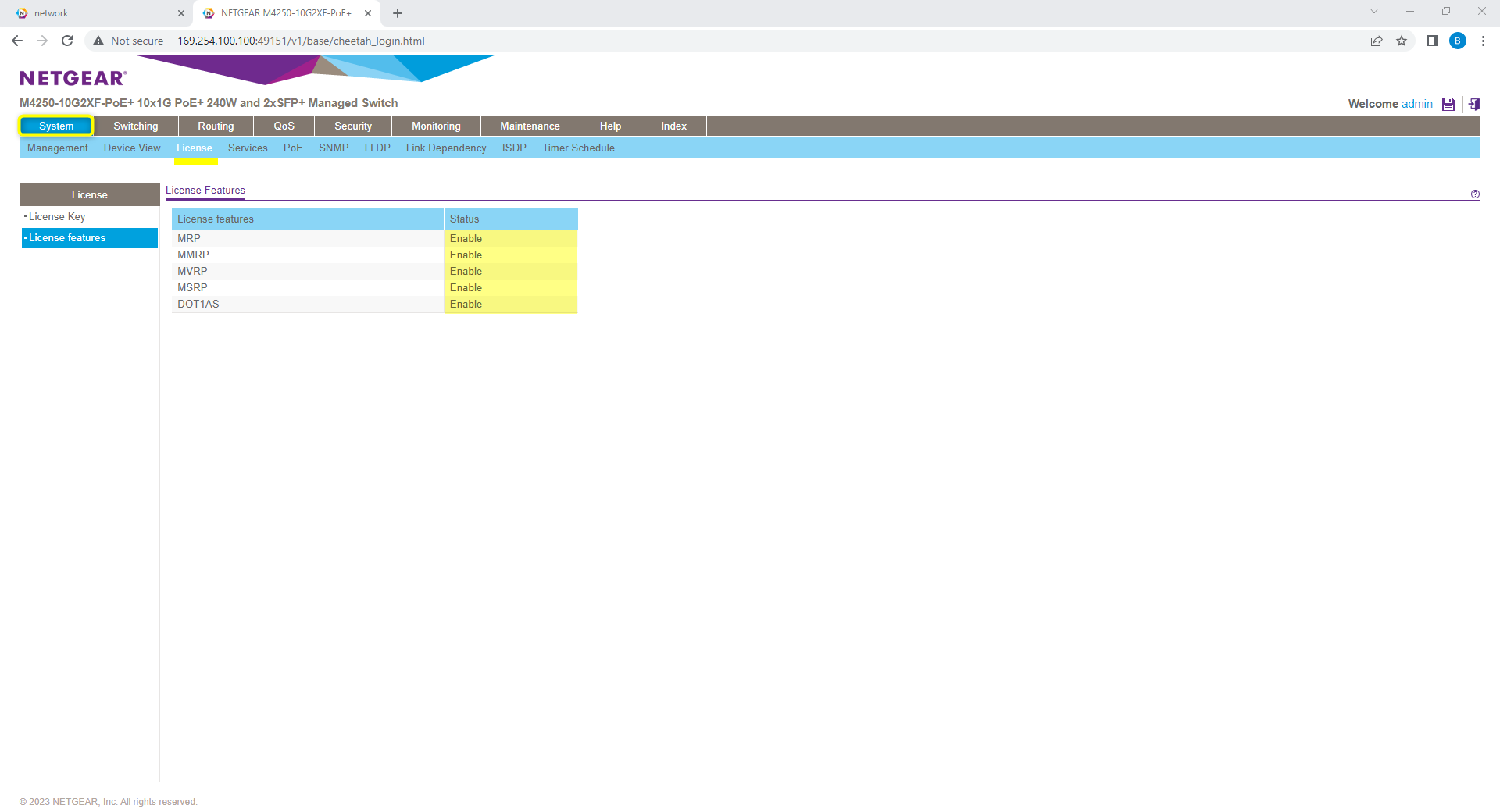
AVB License: Verify AVB license has been installed and active on switch. This may be seen from the System -> License tab.
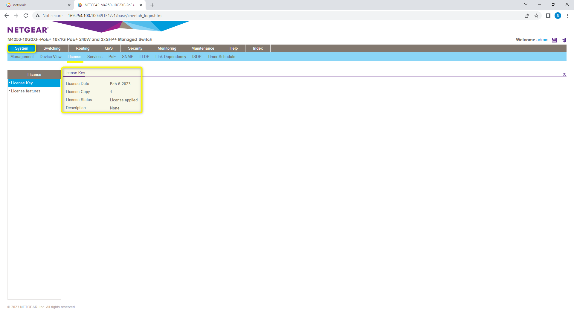
License key will show date installed, and license features should show enabled on MRP, MMRP, MVRP, MSRP, and DOT1AS.
Frame Size: From the Switching -> Ports tab, the “frame size” should be set to 1500 for all ports.
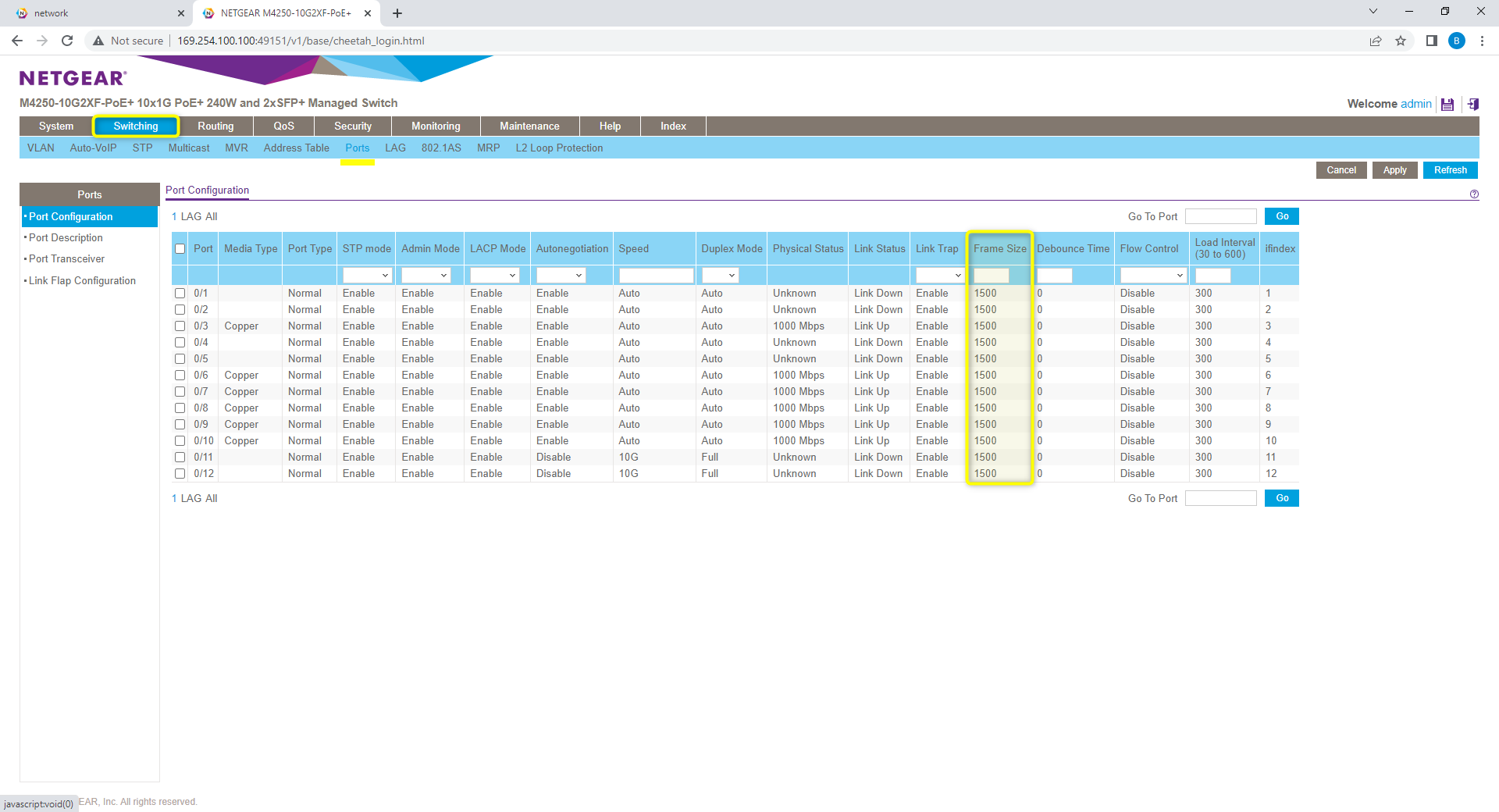
Note: see release notes for Netgear 13.0.5.16 which addresses issue with frame size reverting to jumbo frames (9198) after reboot in a saved configuration. If system experiences this issue, it is recommended to update shipped FW to the latest Netgear version to avoid this issue.
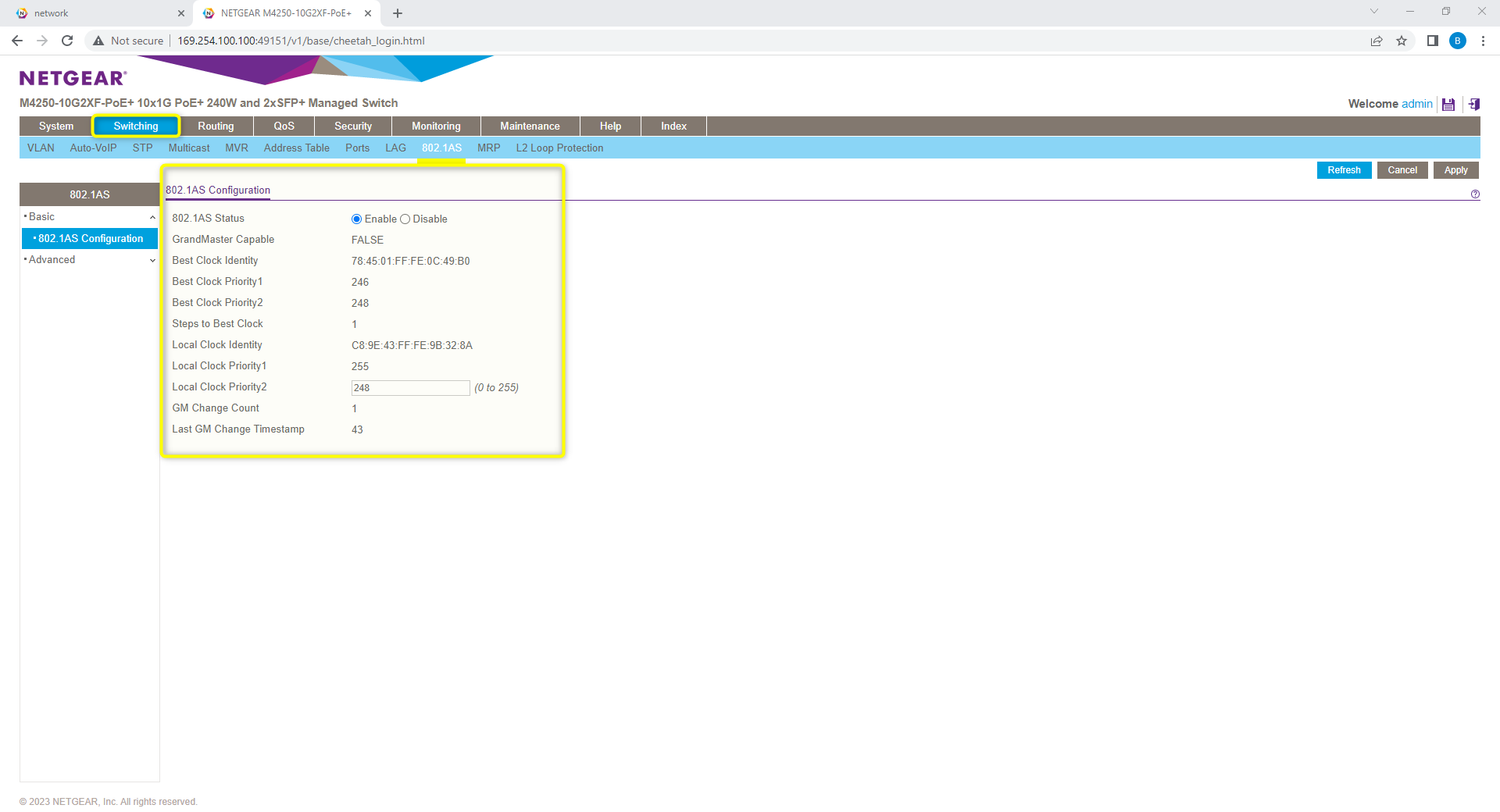
802.1AS settings: From the Switching -> 802.1AS tab, the status should show as enabled with all other values set as default.
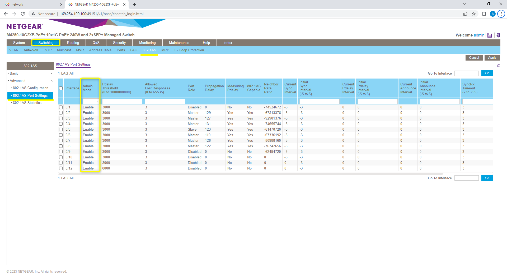
802.1AS settings: From the 802.1AS ports settings menu, Admin mode should be enabled on all ports.
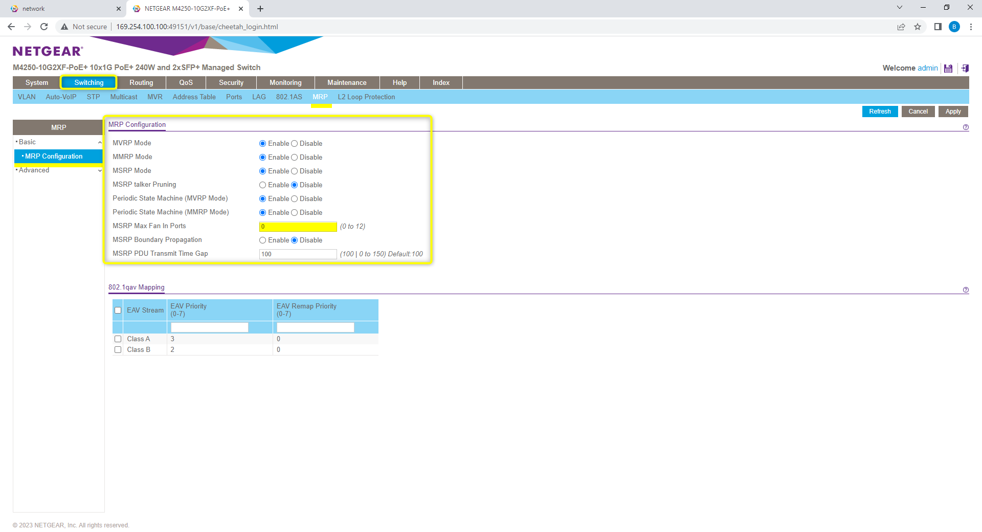
MRP Setting: From the Switching -> MRP tab. verify the MRP configuration Shows MVRP, MMRP, and MSRP modes as enabled. Max fan in ports set to default value of 0.
MRP Timers: From the Advanced->MRP Port Settings, verify Join, Leave, and Leave All timers are at Biamp settings. Join 20, Leave 500, and Leave All 2500(Centiseconds)
Note: (8/7/2023) Default MSRP Leave Timer updated to 500cs / 5000ns to improve compatibility for large AVB networks.

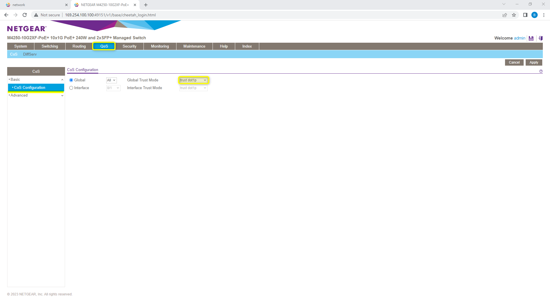
QoS: From QoS -> CoS configuration, verify the Global trust mode is set to “trust dot1p”
Supported Topologies
One of the benefits of the Netgear M4250 line is the ability to scale up the design topology to fit a larger deployment. This is done via the Auto-trunk feature. In the default configuration auto-trunk has been enabled to allow for the single switch to join additional switches in a daisy chain or buss topology to grow with system needs.
To keep the basic configuration of the switch for needing changes while deploying. Biamp has engaged Netgear for best design practices for a simple plug and play topology. Based on typical Spanning Tree maximums or 7 hops, it was decided that a 6-switch daisy chain setup would work best for the plug and play requirement of most Qt X users. Netgear has advised that by going this route we do lose some of the network resiliency that comes with a star topology with the potential of devices offline if a switch lower in the chain loses power.
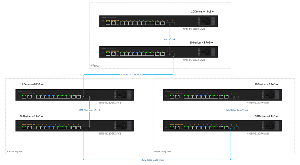
Star topology design will also work for this application and follows the same rules as listed before for Spanning tree. Due to the need to use up additional ports on each core switch in a star topology, Biamp recommends using daisy chain or buss layouts to maximize device count per switch.
For a system requiring more than six (6) total Biamp NMS-NG10GPX-AVB switches to support a design, contact the Netgear design team to plan out a proper topology.
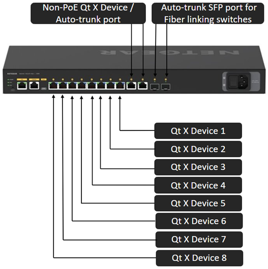
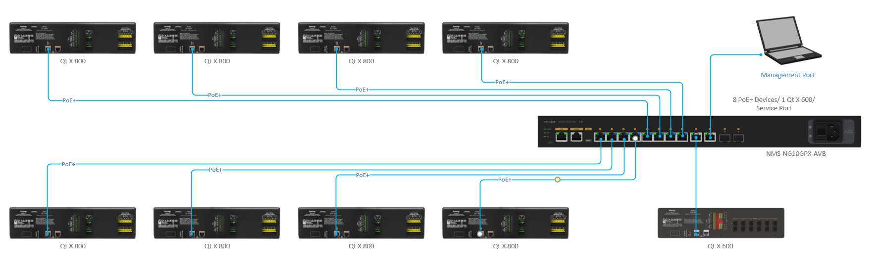
Single Switch
In the single device configuration, the switch can supply PoE power for up to (8) Qt X 800 controllers or support any combination of controller types across the 10 LAN ports. Ports 9 and 10 have the flexibility to support additional Qt X controllers, AVB or Dante input devices, or management PC connections.
Note: Biamp recommends avoiding the use of Fiber media converters on the SFP ports to extend to QT X controllers farther than 100m from the main switch when using AVB. The current peer delay maximum does not support this topology when in AVB mode. These may be used with Dante model controllers while in a Dante-configured state.
All ports may be used for any type of traffic to support the needs of the system. It is important to note that PoE+ power is only supplied on ports 1-8. This allows for 30W max per port.
Qt X topology
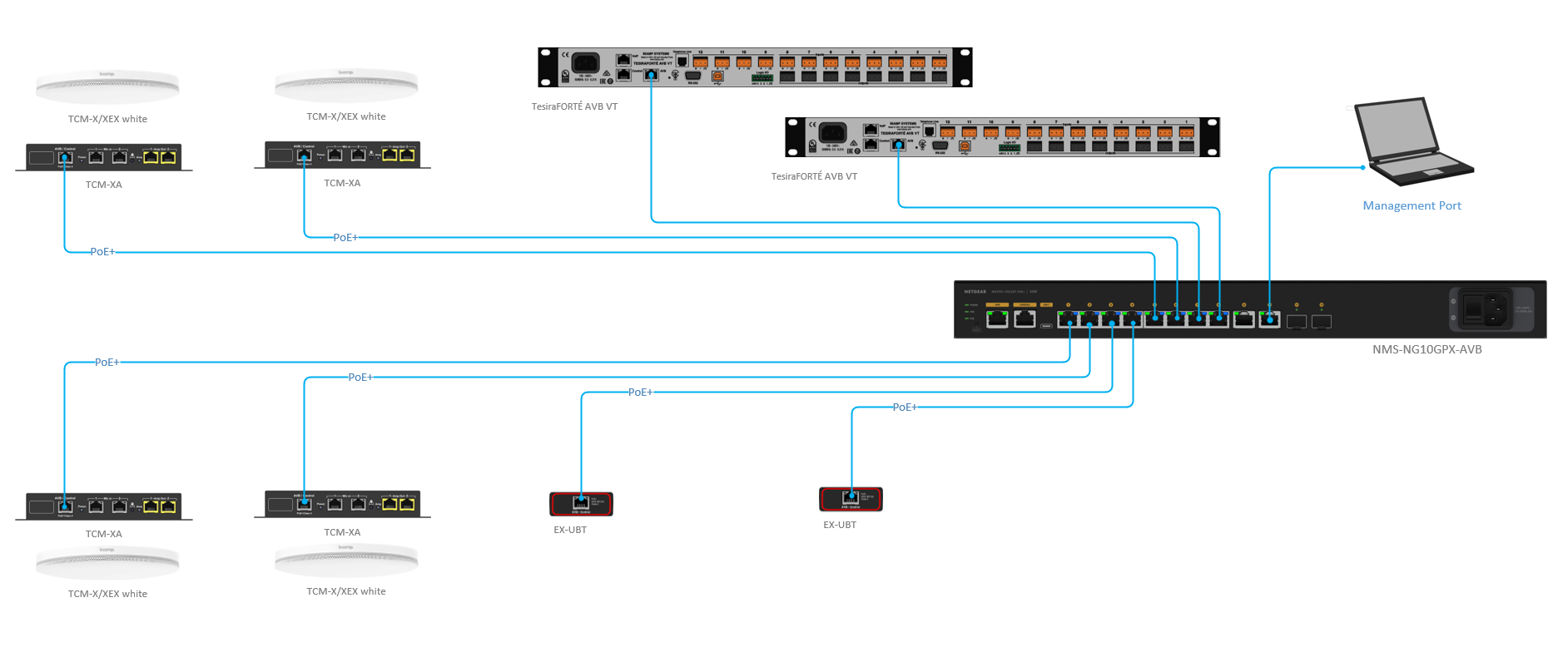
Tesira topology
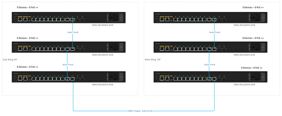
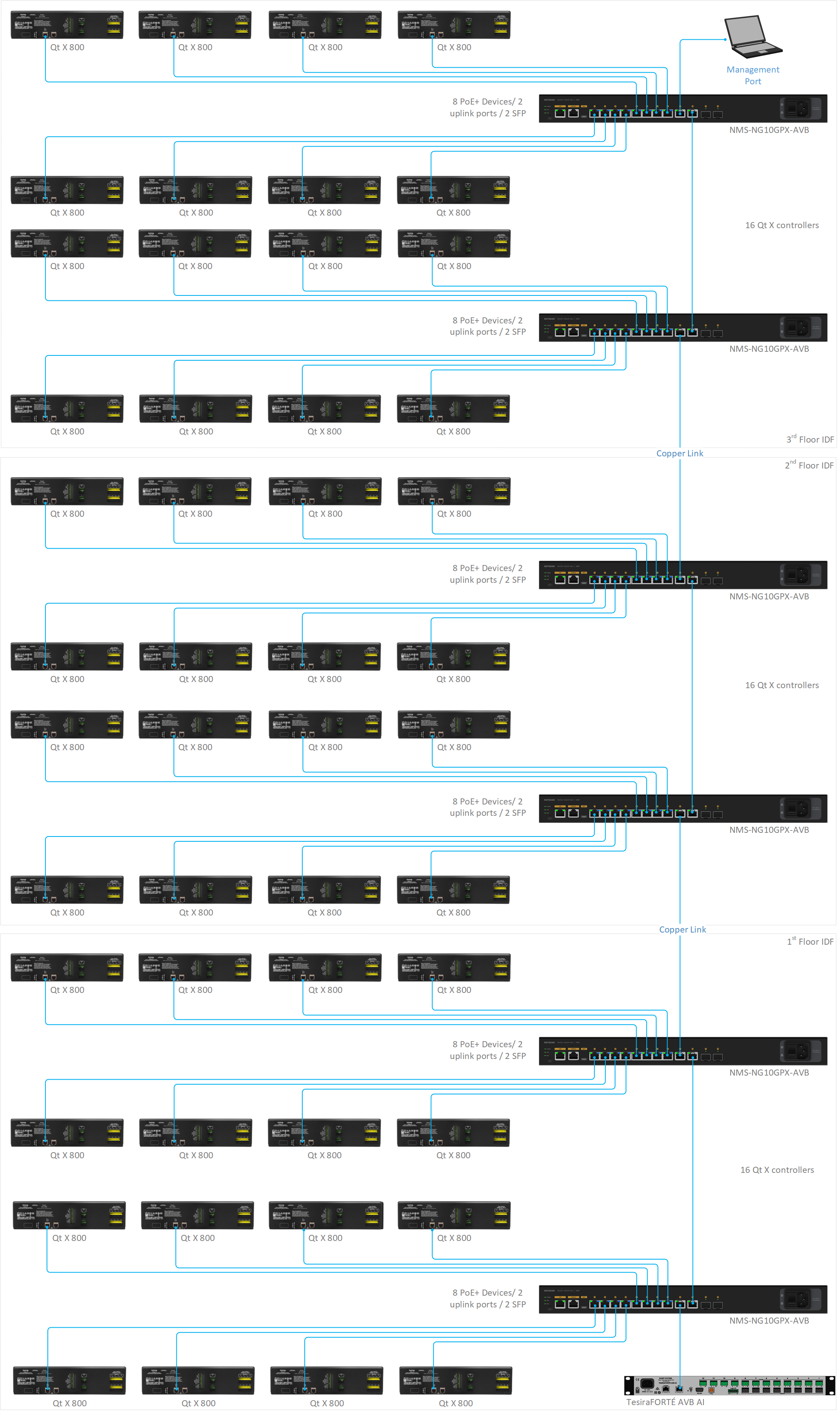
Daisy Chain with Copper Uplinks
In a daisy chain, each switch can supply PoE power for up to eight (8) Qt X 800 controllers or support any combination of controller types across the 8 LAN ports. Ports 9 and 10 are used for uplinks between switches but can also be ued as AVB input locations or PC configuration ports.
- In this topology, only 6 total Netgear switches have been tested and are supported.
- If more switches are used or needed in this design, additional configuration or star topologies may be required.
Switch Topology Example
Qt X Topology Example
Daisy Chain with Fiber Uplinks
In a daisy chain, each switch can supply PoE power for up to (8) Qt X 800 controllers or support any combination of controller types across the 8 LAN ports. Ports 9 and 10 are available for additional controllers not needing PoE, AVB or Dante input devices, or PC config ports.
- In this topology, only 6 total Netgear switches have been tested and are supported. If more switches are used or needed in this design, additional configuration or star topologies may need to be used.
- In the Fiber uplink design, a larger quantity of Qt X controllers or other input devices may be used for a larger total device count.
Switch Topology Example
Qt X Topology Example
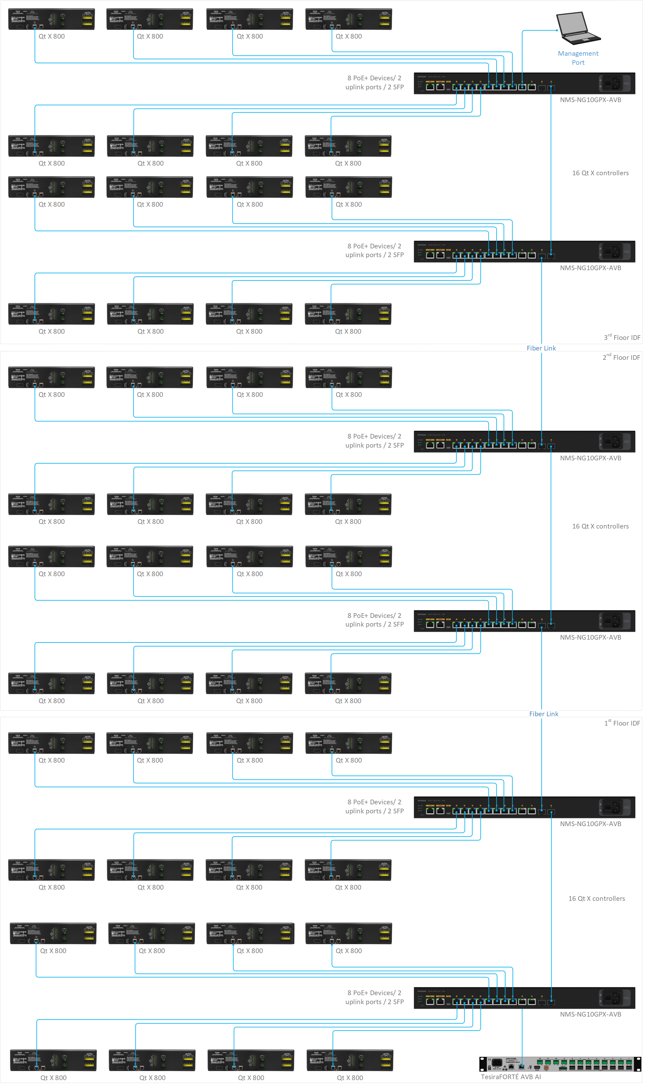
Netgear approved Gigabit SFP modules are recommended when using this topology.