Qt X Programming an analog push to talk source
Summary
Qt X hardware may be set up for push-to-talk (PTT) paging microphones through its analog inputs to allow for zone paging. This article covers setting up Qt X hardware to receive analog audio inputs and program the PTT logic functionality:
- Physical connectivity for analog and logic input.
- Adding an analog source is Qt X software and Web UI.
- Analog input gain staging and phantom power.
- PTT logic programming
- Zone assignment and behavior.
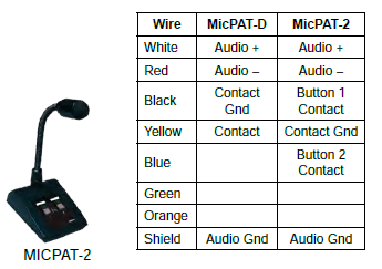
The MICPAT-2 paging microphone is used for this example. This desktop microphone supports two-zone paging. For this example, a single input push-to-talk input will be programmed. The diagram on the right shows the physical wiring from the microphone. The MICPAT-D is also available for systems only requiring one zone push to talk capabilities.
The steps below guide setting up a push-to-talk input from the Qt X software as well as the Web UI.
Physical connectivity
Typical push-to-talk paging microphones have both analog audio outputs grouped with logic pairs in one common cable. Each manufacture follows a unique cable pin-out and color coding. Consult the manufacturer's manual for proper pin-out connections for balanced audio outputs as well as logic contact closure.
When an incoming contact is closed ("Active Low") the audio source shown is sent to all zones selected under the Zone Name dialog. This results in background music being muted in the selected zones and the selected audio source being adjustable on the Zone Paging Level control.
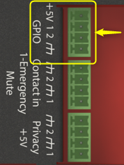
Microphone audio will connect from the MICPAT-2 via the white, red, and shield to input 1 on Qt X controller. Logic outputs (Button 1) black, (Button 2) blue, and (ground) yellow wires will be connected to GPIO inputs 1 and 2 on the Qt X controller.

Note: Contact input 1 is only used for emergency shutoff of the system. Closure across this input will mute all masking and sources for the duration of a closed state. Contact input 2 is designed for a switch-type contact closure and needs to be a low level voltage while in the closed position to trigger. In this use case the MICPAT-2 has a higher closed voltage, so the GPIO contact is used for proper triggering.
Push to talk source via Qt X software
Add an analog paging source via the Qt X software and assign it logic to trigger operation.
Add an analog paging input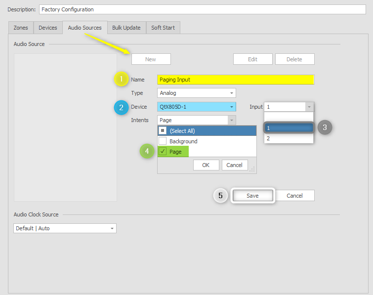
To create an audio source input in Qt X software, select the audio sources tab from the configuration window.
1. Select a new source, then add a unique name. Assign as an analog input.
2. Use the device field to assign the physical controller that the connection is associated with. If multiple devices are on the same network, take care to associate physical assignments with the unit you are working with.
3. Select the input port that is in use for this paging input. In this example, input 1 is planned as the paging mic.
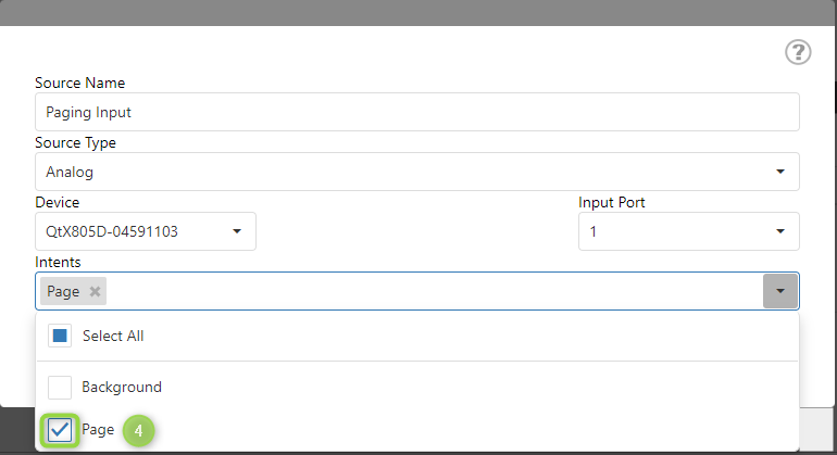
4. Specify the source intents as a paging input. This will make the new input only available as a paging source while not being displayed in the background sources dropdown menu.
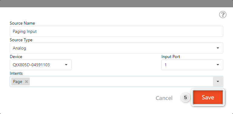
5. Once all selections are made, save the entry to add as an available source. The new source will then be seen in the window with the name it was given.
Existing sources can be edited as needed. There are only two available analog source inputs per controller. Once the source is created, it will be available to select as a source for each zone.
Updates can be sent to the system as each step is completed, or at the end of the process after gain staging and logic is programmed.
Push to talk logic programming
Assign a paging source push-to-talk (PTT) logic functionality and assigning to zones.
PTT functionality is shown using the contact closure logic on GPIO 1. This logic input is selectable as "active high" or "active-low" state. This state is set based on the PTT input device type. For this example, the GPIO 1 will be set to "active low" to correspond to the MICPAT-2 functionality.
In the Qt X software, this is done in the file while offline. After the functionality is added, the updated configuration will need to be sent to the system.
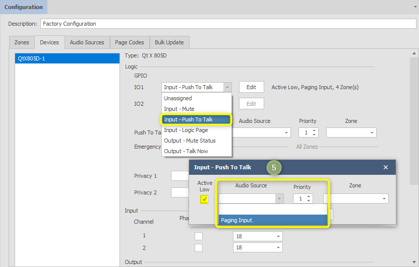
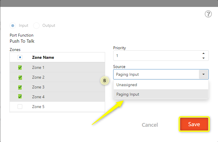
5. Select the device hosting the logic connection from the configuration tab. Select the IO1 location from the dropdown and assign as a "Push to Talk" logic input. This will open a pop-up window. Use the audio source drop-down to select the paging input.
Repeat the steps to add a second push to talk input on IO2.
Note: Priority determines if a page will preempt a page that is in progress. The lower the number, the higher the priority. Therefore a paging source set to Priority 1 will override any page set to Priority 2.
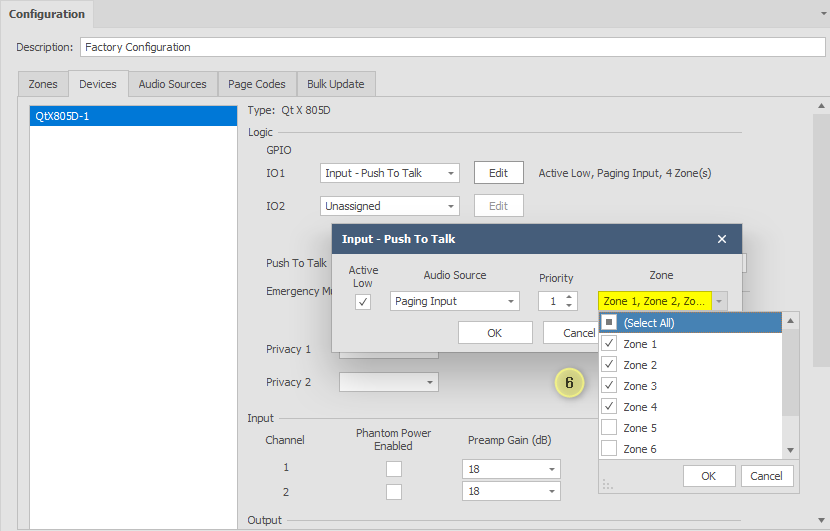
6. Use the zone drop-down to assign PTT functionality to zones. Use the "Edit" button to re-open the popup window if updates are needed.
7. Repeat the steps to add a second push to talk input on IO2.
Analog gain structure
A microphone may need gain applied or the addition of phantom power. Consult manufacturer's spec sheets to review microphone sensitivity ratings and power needs to allow for proper gain staging of the input. Select the preamp gain to match the paging microphone sensitivity and adjust as needed until the desired volume is achieved without feedback in the zone.
In an unconfigured system or while configuring a new system, the input gain adjustments of the analog inputs are located in the configuration menu under the devices tab. Sending the configuration will commit preamp gain and phantom power selection adjustments in this location to the Qt X system.
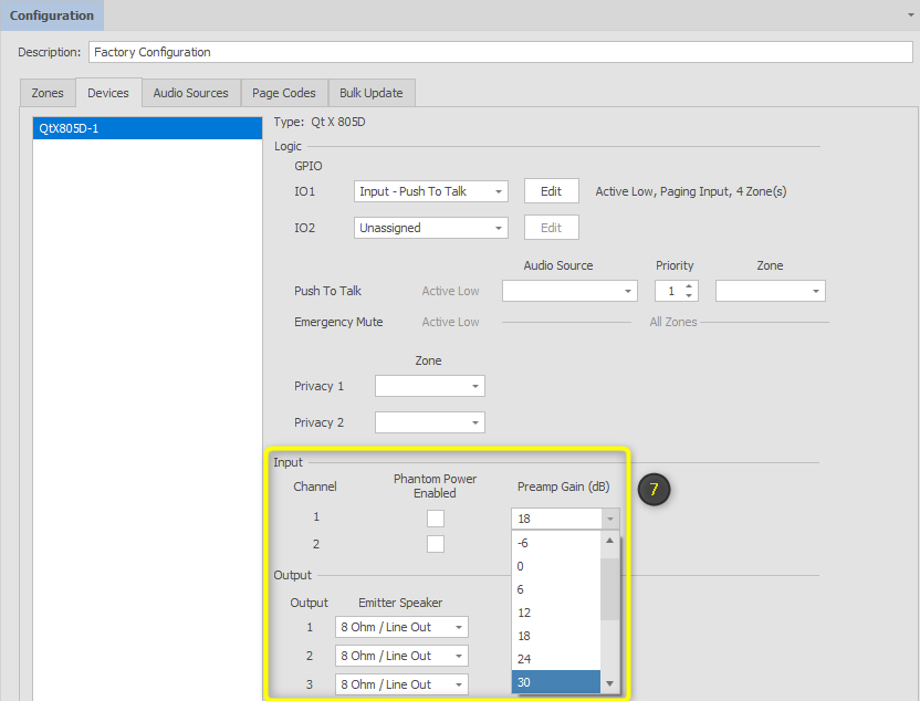
7. Adjust preamp channel gain and assign phantom power where applicable for paging input. This location does not provide any active metering of the input as the gain is adjusted.
8. Once complete, use the "Send Configuration"  icon to send the changes to the active system.
Live Input Settings
Once configured, input gain settings may be adjusted in real-time by selecting the input settings  icon from the systems view. Input gain adjustments from -12 dB to +66 dB are available in 6 dB increments. Select Apply to commit changes to the system.
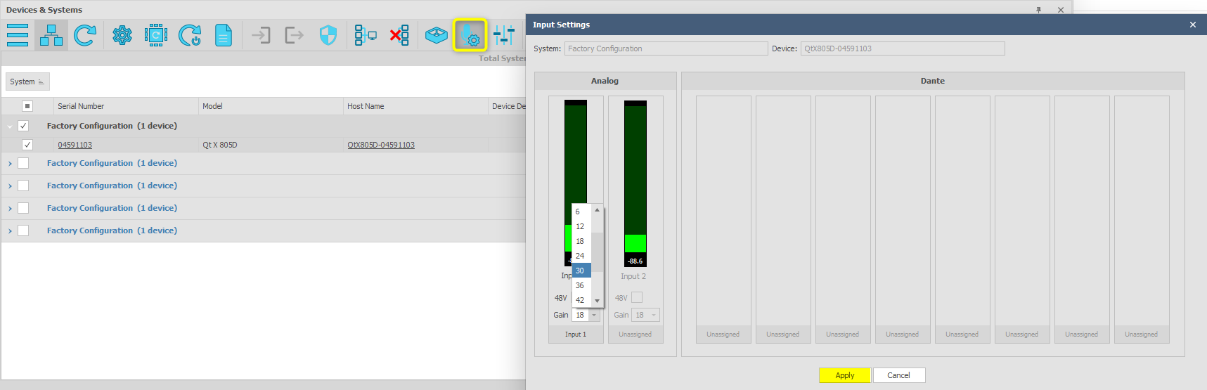
Note: If multiple devices exist within a system, only select the checkbox of the hardware that hosts the analog input to adjust the input settings. A selection of multiple devices will display the input settings tab as grey and inaccessible.
Push to talk testing and adjustment
Test push-to-talk logic by pressing the intended push-to-talk button on the mic. This sets a contact closure "high" across the pin and ground then any background sources present in programmed zones are muted. Once the button is released, the state is returned to "active-low" and any background sources will resume.
Sound masking is unaffected by the push-to-talk functionality. Only background audio sources will mute during the push-to-talk event.
AUX equalizer settings may be applied to the paging microphone input to adjust as needed. Note that the adjustments made for the Aux effects both the Input 1 and 2 channel sources.
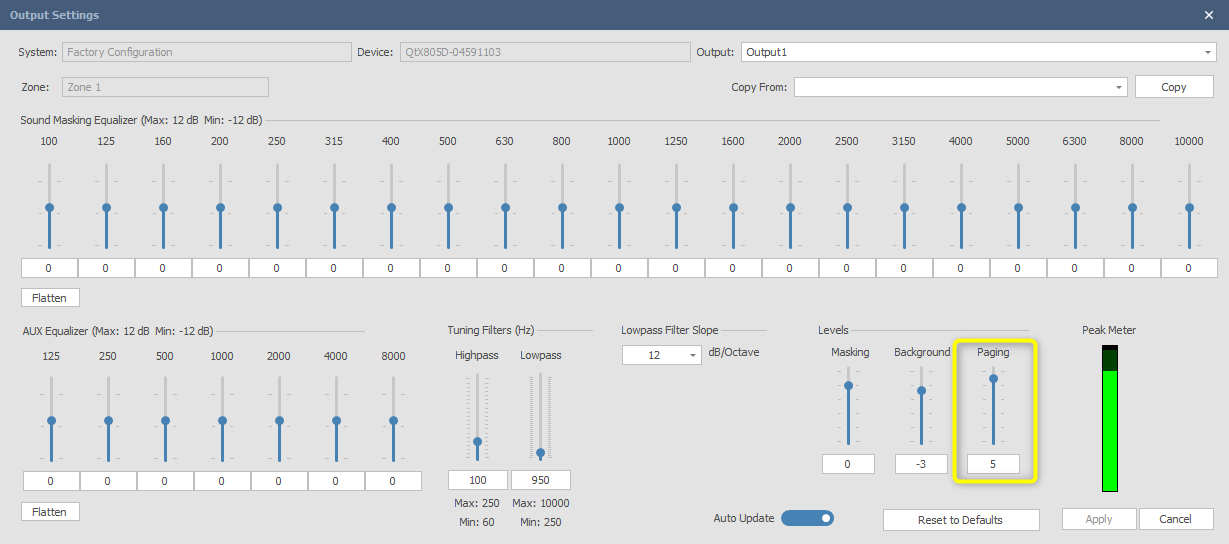
Push-to-talk source volume may be adjusted relative to active masking via the output settings in Qt X software. Only inputs that are triggered by contact closure or GPIO will adjust from the paging level control. A peak meter is available on this page to view the output level.
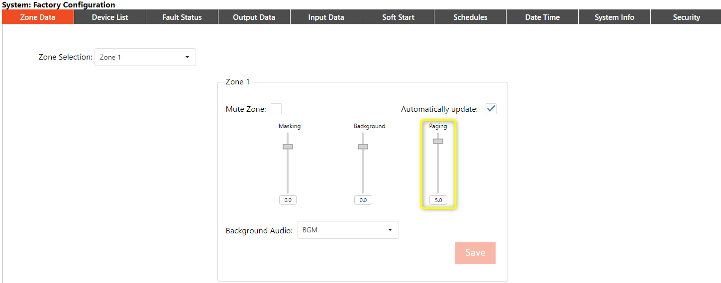
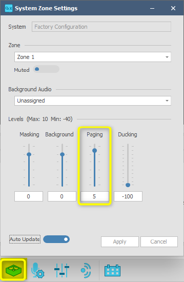
The paging level may also be modified in the System Zone Settings.
Push to talk source via web UI
Add an analog paging source via the web UI and assign logic input to trigger the operation.
Add an analog paging input
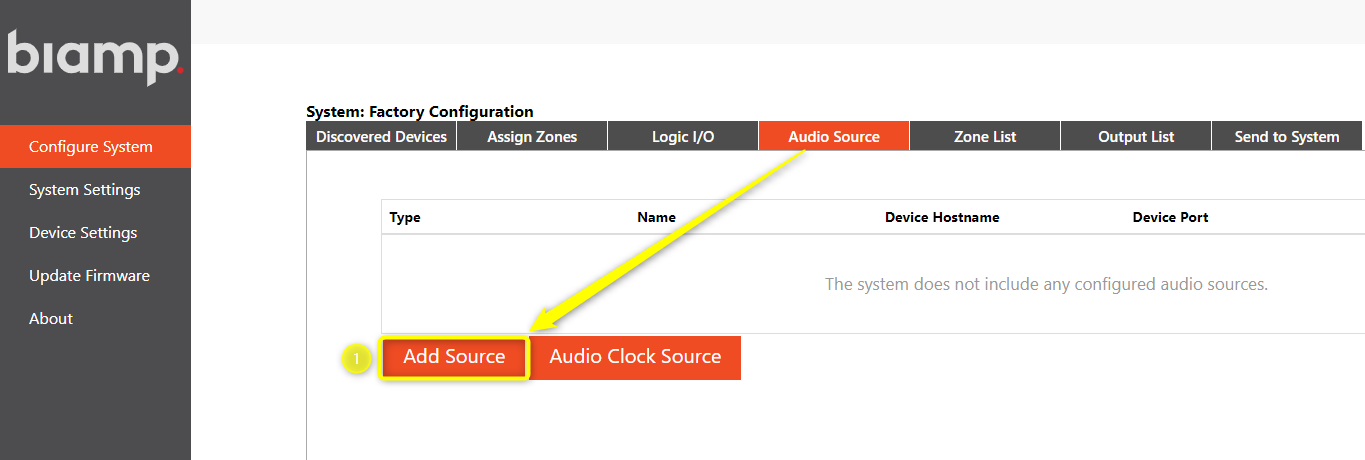
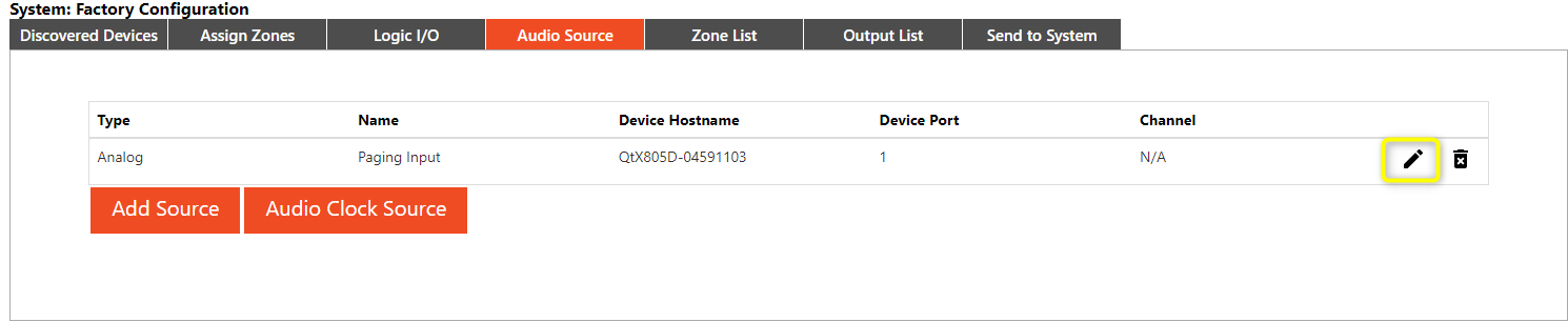
To create an audio source input via the Web UI, select an audio source from the configure system menu. If any sources have previously been added to the system, they will be displayed on this page.
1. Select add source to open the pop-up window.
2. Assign to the physical controller that the connection is associated with in the device field. If multiple devices are on the same network, take care to associate physical assignments with the unit you are working with.
3. Select the input port that is in use for this paging input. In this example, input 1 is planned as the paging mic.
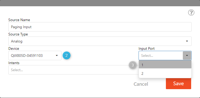
4. Specify the source intents as a paging input. This will make the new input only available as a paging source while not being displayed in the background sources dropdown menu.
5. Once all selections are made, save the entry to add as an available source. The new source will then be visible in the window with the source name it was given.
Existing sources can be edited by selecting the pencil  icon. There are only two available analog source inputs per controller. Once a source is created, it will be available to select as a source for each zone.
Push to talk logic programming
Program a push-to-talk function in the Web UI via the configure system page. PTT functionality is shown using the contact closure logic on GPIO 1. This logic input is selectable as "active high" or "active-low" state. This state is set based on the PTT input device type. For this example, the GPIO 1 will be set to "active low" to correspond to the MICPAT-2 functionality.
5. Select the Logic I/O tab and the pencil icon  from the configure system page to open the programming pop-up window.
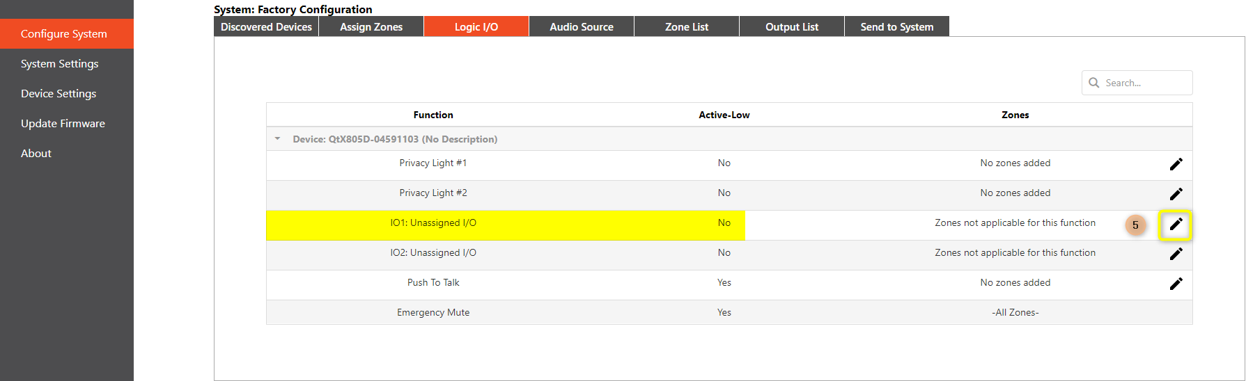
6. The programming pop-up has options to select the source, priority, logic state and zones. The source drop-down will show the Paging Input. The default value for GPIO logic is "Active-High", but in this application the microphone will provide a contact closure when ready to page. In this setup, we will want to enable for "Active-Low" logic operation. This will allow a page to be active while the contact is in a high state.
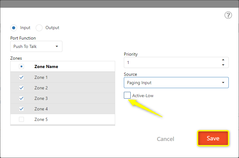
Note: priority determines if a page will preempt a page that is in progress. The lower the number, the higher the priority. Therefore a paging source set to Priority 1 will override any page set to Priority 2. Review all settings, and then select Save.
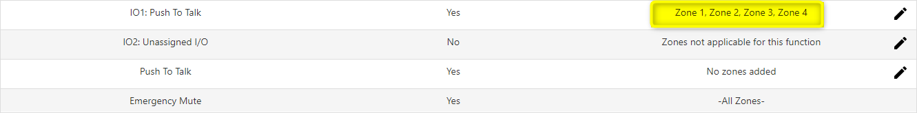
Each assigned zone from the previous step will appear in the Push to Talk row for easy verification.
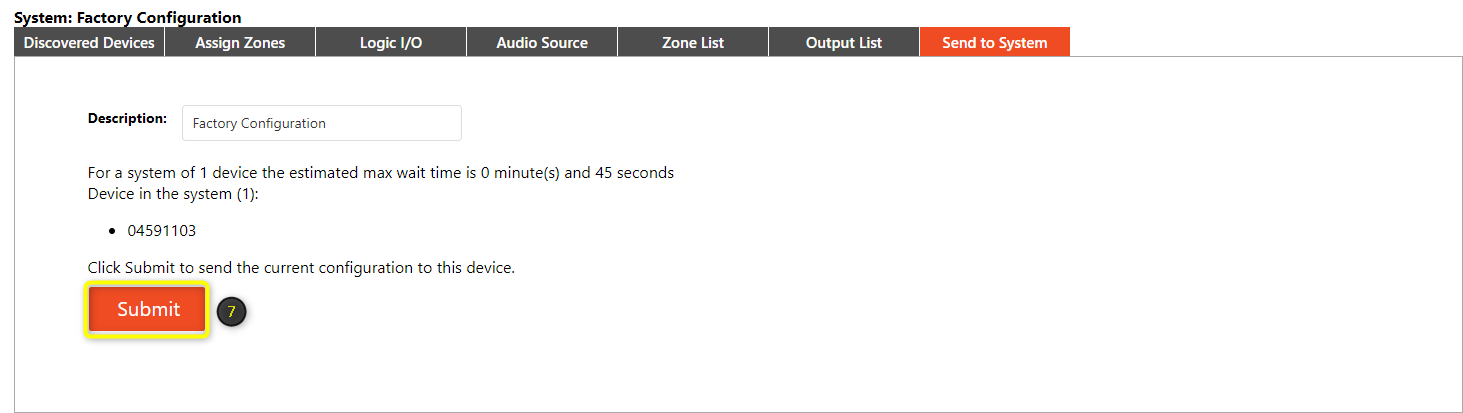
7. Use the Send to System tab to Submit the push-to-talk logic updates to the system configuration.
Analog gain structure
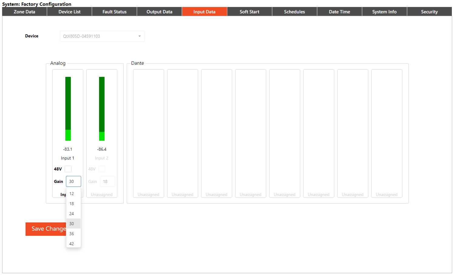
The audio source gain adjustment is located on the System Settings page, under Input Data. Analog sources can be added offline via the configure system page, but gain adjustments cannot be made until an active configuration is sent or currently running.
8. Input gain adjustments can be adjusted while viewing the peak meter to assist with gain structure. Input gain adjustments from -12 dB to +66 dB are available in 6 dB increments. Once set, select Save Changes to commit to the active configuration.
Push to talk testing and adjustment
Test push-to-talk logic by pressing the intended push-to-talk button on the mic. This sets a contact closure "high" across the pin and ground then any background sources present in programmed zones are muted. Once the button is released, the state is returned to "active-low" and any background sources will resume.
Sound masking is unaffected by the push-to-talk functionality. Only background audio sources will mute during the push-to-talk event.
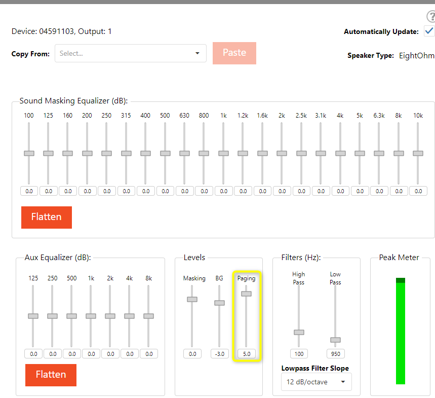
AUX equalizer settings may be applied to the paging microphone input to adjust as needed. Note that the adjustments made for the Aux effects both the Input 1 and 2 channel sources.
Paging level adjustments
Push-to-talk source volume may be adjusted relative to active masking via the Output Data tab level icon  on a zone-by-zone basis. Only inputs that are triggered by contact closure or GPIO will adjust from the paging level control. A peak meter is available to view the output level.
Paging level may also be modified in the Zone Data page.